Help in Understanding what I see2

djmiyta

Well-known member
I have a cheap amazon transistor tester and as far as I know it works just fine. When I throw a 2n5089 in the tester I get a readout that says
NPN 123=CBE

hFE = 430 Vf=680mv
and over here is the schematic symbol of the transistor
ICE0= .00mA

ICEs=.00mA

Now when I go to the Datasheet for 2n5089 I'm lost . Hfe is the only one I can find on the data sheet but I see it in a couple of places . For the above my best guess is Vf = forward Voltage (?) the next 2 ICE0 and ICEs I have no clue and more so whether the tester info is useful for building pedals. so that's what I'm asking is how or what to look for when comparing the tester to the data sheet
the data sheet shows
DC Current gain using different milliamps so how do know the tester is testing in the same manner do I have to do some conversion with math? I understand if I'm asking in a non sensible way and if it starts involving algebra to de cypher the above forget it cause basic math skills is what I got.(barely)

for the XTS Atomic OD does the hfe on the 2n5089 need to be any specific number (thats how I got going on this whole thread) the above is a typical readout of around 20 that I checked only a few old ones read hfe at 750-800 hfe which I thought was typical so I wonder if I got some shitty trannies cause I got about 50 of em.

Thanks to everybody here on this great forum for wasting their time reading about my lame issues and going further and answering them.
 
Last edited:
  • Like
Reactions: fig
Your issues aren’t lame if you post them and get a response that helps you better understand something and get a pedal to work — other people (like me) will then be able to learn from the thread, too.

Our tutors’ greatest test of their knowledge and understanding of it is whether they’re able to pass it on.

So it isn’t a waste of time.
Hopefully a solder-sifu will be along soon to teach us…


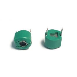
BTW, I’ve got several values of those pF trimmer-caps up to 60pF the largest value I’ve seen available is 100 pF. I’ve put one in my Rat clone to test different op-amps etc.
Thank you for the kind words and for the trimmer caps when I saw them just thought they could be really useful just didn't exactly know how but I did know someone else would very cool
 
HFE in the 4-500 range is probably enough for most circuits. I believe Vf is the base-emitter voltage (0.7V is very typical for silicon). Those two currents are leakage current. My EE is a bit rusty but I think it’s the current that flows from base to emitter (measured in different conditions) which ideally should be exactly 0 but it’s always some small amount. The lower the better (unless you are making certain kinds of fuzz) as most circuit designs assume it’s close to 0.
I hope that helps!
 
Thank you and yes it does help. But what I don’t know is what info do I take from the tester to compare to the data sheet and how do I know the transistor I’m testing is tested under the same conditions?
 
  • Like
Reactions: fig
In the datasheet for the 2n5089 you find a few parameters, e.g., hFE measured at different collector currents and different frequencies (I assume DC and 1kHz) ranges between 400 and 450 min, ~1K max, so it's consistent with what you see. Icbo is collector-base current with the emitter being open, at most 50 nA (so close to 0!), which gives you Iceo by multiplying by (1+beta)=(1+hFE), i.e., about 450 times that, which is 22 uA (still close to 0 for our purposes). Ices is the collector-emitter current with base connected to emitter, not sure how interesting that is (also not in the datasheet afaict). Vbe in the datasheet is 0.8V, close to what you measured (680mV).
So I think you have some decent transistors in your hands!
thank you very much. great info. although I find it a bit difficult to follow most of what you say as crazy as it sounds it would awesome if there was a way to post your specs of a particular tranny and find out right away if yours are within specs ( for those of us that find it very difficult to understand electricity and its jargon) believe me I do try to absorb all I can maybe if I was a cow with 7 stomachs I could absorb more but I'm not. It's a work in progress
 
Data sheets are all slightly different from each other so you just need to keep reading different ones until you understand the terminology. You can look up each of those symbols to refresh your memory (I know I need to!) but once you’ve done it a dozen times, it starts making more sense faster.
 
You may want to go through Chuck’s Boneyard. There’s a TON of info that he wrote about the weird, quirky items in the pedal building world

A word of warning: trying to absorb everything he writes about at once is like drinking out of a fire hose. It will take a few reads to get it unless you’re an EE
I’ll heed that warning they’re still finding my teeth from the last time. I have read most of his stuff if he moronitized it I’d absorb it a tiny tad faster ( not asking you do that Mr. Chuck I’m just saying I have difficulty grasping basic concepts of electricity and electronics and it’s me not you or your fantastic explanations) so aside from actually immersing myself in an electronics course …….. I just throw it out thar and see what I hook to see what sticks( did I mention my memory issue ? I can’t remember
 
I don't have a clue about how most electronics work but that doesn't stop me from building pedals, tweaking and redesigning bits here and there to suit myself better, etc. I don't understand most of the stuff on a transistor datasheet but it seems that you don't really need to most of the time. And I strongly suspect that a lot of boutique pedal designers don't know much more than me! And now with this forum I am more adventurous than ever because I can get help. Chuck is a prince among men for his knowledge and willingness to share it, and there are others here like that too.

I wish I knew more and I try but my brain isn't wired that way.
 
My EE teacher always used to say: “a transistor has 3 sticks”, meaning that once you understand the basic configurations you are done. I don’t think he was a very good teacher tho!
 
Some things to keep in mind when reading the datasheets:
1. They list the manufacturer's pass/fail criteria. 👍👎
2. The test conditions rarely, if ever, bear any resemblance to the conditions in your circuit. :rolleyes:
3. At least half of the line items will be of no interest to you. 🥱
4. If you don't read any other part of the datasheet, be sure to read and obey the absolute Maximum Ratings. 👮‍♂️
5. The parameter you are most interested in isn't listed. :poop:
My experience exactly! Except that I don't know what most of the abbreviations mean. I will read them, however, and nod knowledgeably as if I do understand. Just in case anyone is watching.
 
Here's a quick rundown. Refer to the attached datasheet which contains two of our most commonly used transistors. The left column provides a description of the symbol (acronym, mnemonic) in the 2nd column. Test conditions are also provided in the left column. The Min & Max columns are just that. Real parts land somewhere in the middle.
Absolute Maximum Ratings Stay below 75% of these numbers for maximum reliability.
Thermal Characteristics Usually not a concern in guitar pedals because the power dissipations are 100mW or less. Usually way less.
Off Characteristics Breakdown voltages are same as Absolute Maximum Ratings. Cutoff current is another term for leakage current.
Icbo = collector-to-base leakage with emitter open (not connected). Essentially the same thing as Ices (collector-to-emitter current with base shorted to emitter).
Iceo = collector-to-emitter leakage with base open. Not proportional to hFE unless the transistor is very leaky.
On Characteristics DC current gain is collector current divided by base current. hFE influences biasing. See fig 8 for how hFE varies as a function of Ic & temperature.
Collector-emitter saturation voltage, we don't care in pedals.
Base-emitter on voltage, this is an extreme case we don't see in pedals. Assume Vbe is 0.6V for silicon and you'll be plenty close. See fig 9.
Small-Signal Characteristics The only one we care about here is hfe. Notice that it's the same (or nearly so) as hFE. This may or may not have an effect on pedal performance, depending on the specific circuit. I talked about hFE in detail in Chucks Boneyard.
Don't bother comparing noise figure between transistors because a) most datasheets don't list it; b) the test conditions don't usually match the pedal conditions. If you want to get into noise analysis, you have to refer to figures 2 - 7 and most datasheets don't provide that info.

That's it in a nutshell.
 

Attachments

  • 2N5088-2N5089.PDF
    83.6 KB · Views: 3
Once again thank you all for the help info and advice. Some of it is actually starting to make a little sense. And I too have building pedals for years only knowing what end of the soldering iron to use just that as I’m getting older I’d like to know a bit about what I’m building. Why ? Curiosity is really it. I’d say aside from minor troubleshooting and occasional major troubleshooting my percentage of working builds working first time is up about 80-85% which out of seriously hundreds of builds (somewhere between 300 -350 over the past 18-20 years ) is not too shabby in my opinion but one of the reasons I come here to this forum
Thanks everyone again it’s really really appreciated
 
Back
Top