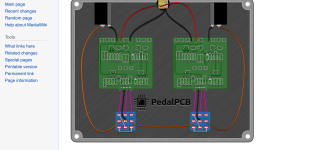
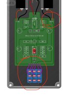
It's really easy. Starting from the footswitch for the compressor, grab the wire coming from the footswitch's OUT terminal. This is the one that would normally go to the output jack. Then connect its other end straight to the Sproing's footswitch's IN terminal. This is the terminal that, in the diagram above, is shown connecting to the far left solder pad of the Sproing board. It's the middle terminal on the left hand column of the footswitch. We're going to leave both that solder pad and the IN pad of the Sproing board unconnected. Then, connect the OUT of the Sproing board to the output jack like normal.