How to add bicolour LED to a two-speed Forum Vibe?

Hello. First time posting here. I can't find info on this that I can understand. So I have built a Forum Vibe with two speed pots and a 3PDT switch to switch between the two pots. I want to add a bicolor LED that will indicate both LFO speed and change colour depending on which speed pot is "on". Can anyone help?

General context: I've built a few pedals but my electrical knowledge is limited and I can't really read schematics...
 
Last edited:
How do I figure out if I need common anode or common cathode? It appears I have used a common cathode LED, so presumably I need a common anode one? But also, what do I have to do to get it to flash with the LFO speed?
 
It's determined by where the LED gets its power and the easiest way to implement a switch

If you want it to flash with the LFO then you are probably going to want to use a common anode LED so both colors will get their signal from the LFO, then you can install the CLR's on each neg lead and wire those into the foot switches
 
I haven't looked at the schematic—so I'm not sure if you need all the poles on the 3P2T switch to go from 1 pot to the other. (I'd think if the pots get a ground to one of their terminals, that wouldn't need to be switched, it could be left on . But If this is wrong, and you actually need all the poles, then you will want to get a 4P2T switch.
 
I haven't looked at the schematic—so I'm not sure if you need all the poles on the 3P2T switch to go from 1 pot to the other. (I'd think if the pots get a ground to one of their terminals, that wouldn't need to be switched, it could be left on . But If this is wrong, and you actually need all the poles, then you will want to get a 4P2T switch.
Looking at the schematic, nothing on the pot(s) are going to ground — However! ...


The dual-ganger SPEED is wired as a rheostat (both gangs), not a voltage divider.
Need two poles for each input to GangA-3 lug & GangB3 lug, but the outputs are all going to the same stream ie lugs GangA2&1 and GangB2&1 are all tied together.


3PDT should be doable.


@Solder of Destiny ...

May or may not help to have a look at this SWITCH-CRAFT thread:


Here too:

 
Thanks for the responses. I was flattering myself when I said my electrical knowledge was limited. In reality, when I build a pedal I am painting by numbers.

I have no idea how to go about this.

If it helps, I've wired up the pedal like this


RDT_20251016_2121195090592315597757017.png

With serial switching between the 2 x two-gang speed pots, as below:

Screenshot_2025-10-16-20-44-10-178_com.android.chrome.jpg

Which leaves one pole of the 3PDT switch free (as per diagram), at least in my understanding.
 
Last edited:
Thanks for the responses. I was flattering myself when I said my electrical knowledge was limited. In reality, when I build a pedal I am painting by numbers.

I have no idea how to go about this.

If it helps, I've wired up the pedal like this


View attachment 104829

With serial switching between the 2 x two-gang speed pots, as below:

View attachment 104830

Which leaves one pole of the 3PDT switch free (as per diagram), at least in my understanding.

Uhm, I could be wrong, but I don't think that's going to work.

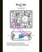
I think the two gangs' different lugs on each pot need their own poles...


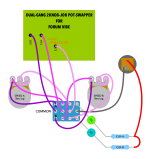
Here's my approach...
DUAL-GANG 2-KNOB JOB.png

I've drawn it up for a 4PDT with separate CLRs as one may need to adjust the brightness of the different colours chosen for the LEDs.
I opted to lay it out with a 4PDT for two reasons:
1) Ensures absolutely ZERO-INTERACTION between the 2 x dual-gang pots;​
2) Extrapolating this diagram for other builds.​
You could build this on a 3PDT and just route all the light-pink wired lugs above to S2 on the PCB, there may be some interaction between the pots, but negligible if you dial in the two-presets before a show (assuming you don't need to change anything for other songs/tunes mid-performance).
 
Ok so there are two different things we are trying to do: Make the indicator LED bicolor, and make it flash with the LFO. First we are going to do the bicolor.

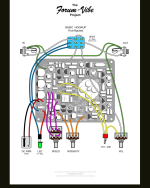
The pic above that shows the speed footswitch and the line "use these pins for a bicolor LED" is a big hint. There are two different kinds of bicolor: Common anode and common cathode. On an LED, the anode is the + leg and the cathode is the - leg. There are two different versions to allow for flexibility when designing or implementing one of these components. In this case we are going to use a common cathode because it's what fits easiest.

In the diagram, find the LED + solder pad. It has a red wire coming from it that goes to the LED, then the other leg of the LED has a blue wire that goes to the on off switch. Here's where we start to modify. Remove the red wire from the LED + solder pad and remove the blue wire from the LED cathode.

Now, locate the 3 unused terminals of the speed 3pdt footswitch. Make a new wire that goes from the LED + solder pad to the middle of these 3 pins. Then grab your common cathode bicolor LED and figure out which pin is which. Figure out what color you want fast/slow to be. For example, you could do Fast as red and slow as blue. Make a wire that goes from the pin on the switch that is associated with the fast speed and connect it to the red leg of the LED. Then make another wire for the blue side. After this, grab the wire we disconnected from the original LED's cathode and connect it to the bicolor LED's cathode.

The LED current limiting resistor will be okay for both colors, but if you find one is too bright, then just add a small resistor in series with the LED on the side you want to make dimmer. For example, if the blue is too bright, then disconnect the wire going to the blue anode of the LED, solder a 1k ohm resistor to the anode instead, and solder the other leg of the resistor back to the wire. 1k is just an example value, you can play around with different values until you find the one you like.

Try this first and then we'll work on the LFO, as it's a bit more involved
 
Below is the documentation's advice for incorporating a speed indicator LED (though again I can't read schematics), for whatever it's worth. But I've built this Uni-vibe in a JJ enclosure so I doubt if it'll be possible to squeeze another mini-board in there.

Screenshot_2025-10-19-07-44-49-646_com.android.chrome.jpg
 
Quick mention that there are a few different choices of bicolour LEDs:
Red/Green​
Red/Blue​
Blue/Green​
Amber/Green​
Amber/Blue​
...and others if you hunt.
 
Back
Top