How to figure out the specs of this opto coupler?

geso

Member
I want to copy and modify this pedal to suit my needs, because as it is, it is not very usable. It is a pretty simple build on its own, connection routes are visible, only normal sized components, the compressor is noise and distortion free, so would be a good starting point. But the only problem is: the opto coupler in it seems to be a custom made one. It is not one that is usually available with plastic housing, but a sealing tube is pulled onto it and the whole thing is tubular shaped, so I guess it is an LDR/LED glued together.

How could I figure out the values of the optocoupler components to copy that as well for the circuit? If it is not possible to get the values for it, if I re-create the schematic can that give a clue for which opto coupler could be a substitute?
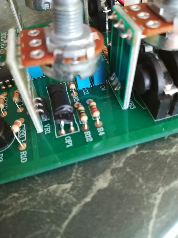
Here is the photo:

IMG-20260430-150933.jpg
 
If you can remove it carefully, it's very easy to breadboard a tester.

Set up a simple breadboard with 9v supply through a CLR resistor. Like 4k7.
Plug the negative leg on the LED side of the optocoupler inline with the resistor. The other side to 9v power rail.
Leave the LDR side of the legs free and clip your multimeter leads to these two leads on the LDR side.
Set the DMM to resistance.
Apply power. You should see the resistance jump up to whatever. 500k-1m, etc. This is your light resistance.
Remove 9v power. You should see the DMM jump up to 500k-10m. This is your DARK resistance.
How fast it gets to a stable dark resistance reading is your recovery speed (not sure what the technical term is for that).
This will give you the spec's of the opto and you can recreate it with your own LED/LDR combo or find a vactrol that matches.
Oh and have fun:)
Ahh, thank you very much for the simple and precise description! The only one so far that I understood! :D
 
Back
Top