Hydra delay

mybud

Well-known member
Build Rating
5.00 star(s)
hydra_gutshot.jpg hydra_outside.jpg
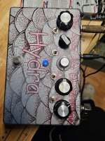
After a long layoff from building, I completed this build yesterday. I found that (like practising) given enough time away from a regular task, one's chops tend to deteriorate but I was itching to build this.

It's a great sounding circuit as many others have reported but I need to do some careful retouching work on the switch soldering, where I notice I've missed a couple of spots. Hence, switches 1 and 2 don't do much but I'll get to them in time.

Sound-wise I like the rhythmic delay aspect, where different combinations of switches provide lots of options. I'm giving the build its full complement of stars for its fun aspect. As far as my own competencies go, I probably deserve no more than two but things will improve (I trust) as I get back into building more regularly.

I have picked up a popping noise problem, which I'll post in the troubleshooting thread. Apologies for the duplication but I don't want to confuse by posting different (conflicting) issues in the same thread and spoiling an otherwise very positive build report.

Thanks for reading as ever. NGBS, as @fig says.
 
Hey Bud,
The instructions seem a bit Lax. where did you wire the LED and what is wired to the A K above the footswitch? I've got a mess.
 

Attachments

  • 20250503_114627.jpg
    20250503_114627.jpg
    842.2 KB · Views: 19
A and K refer to the positive (longer leg side) and negative leads of the LED respectively.
To expand on this, the letters come from (A)node and Cathode (spelled with a K, possibly due to coming from a Greek word which starts with a K, and to distinguish from caps or collectors which start with a C). To be honest whenever I put in LED's I usually check the LED polarity thread on the forums just to be sure which one was which.

As for the build itself, I think it looks nice and tidy! The switch soldering is indeed not great, but you already identified that, so it's just a matter of fixing it. I think all the legs should look like the middle leg on the leftmost switch, or the top legs on the two rightmost switches. Similarly some of the pot legs seem to suffer a little from the same thing. https://learn.adafruit.com/adafruit-guide-excellent-soldering/common-problems has nice examples of what is good and what is not.

To be honest I'm a bit insecure about my pots too, sometimes, and for that reason I sometimes also hit the pots on the other side of the PCB too - although tbh I don't think I've had any cold solder joint issues in ages, and overall I've only ever had it a handful of times over dozens of builds. Most commonly probably in the offboard wiring, even, where I instantly notice the issue on the first test run.
 
Thanks Guys.
I have everything upside down. And I have a 100K where a 10K should be. And I notice the 50K should be a C. this explains some of the problems. If I get the LED right I am on track to get it straight.
 
Thanks Guys.
I have everything upside down. And I have a 100K where a 10K should be. And I notice the 50K should be a C. this explains some of the problems. If I get the LED right I am on track to get it straight.
You’re welcome and best of luck getting things sorted.
 
Back
Top