Ideas needed for bass guitar filter/distortion pedal effect

Grubb

Well-known member
Not strictly a PedalPCB question, but hopefully someone will weigh in with some ideas. A colleague at the school I work at is a drummer in an alt-rock band in my local area. They are in the sound design process for a cover of Radiohead's Climbing Up the Walls:

The bass guitar is going to do the low synth swells you can hear in the intro/first verse. They would like my help in building an effect that combines a bass-friendly distortion (I'm thinking a Rat-type) with a foot-controlled (wah-style) sweepable low-pass filter that lets highs and distortion back into the signal as the toe is depressed. I'm thinking a clean blend might also be handy to allow the amount of original signal passing through the unit to be controlled. It sounds like it should be pretty achievable.

1. What would you use for this in terms of wah/rocker hardware?
2. Effect order - distortion then low pass?
3. I've seen some simple high-pass filter circuits online, any recommendations for ones that might suit this application?
4. What pot type and value would you be thinking for this?
5. Any PedalPCB boards/mods that might be helpful for this effect?
 
I've done a bit more thinking about this. So far I've got Rat with bass Contour mod selected for the input side of the pedal, then an Eric Archer DIY-LPF circuit on the output side. I'll add an expression jack to give external pedal control to the Freq pot. Also considering an order switch.
 
Rats aren't terribly bass friendly from what I've read, hence the many mods online to regain some of the bass lost — I also used Tranter's 2nd mod (see below) for my recent Rat build and once modded, I thought it sounded great with my upright!

Gord Tranter's bass mods for the Rat, as used by Marcus Effects:

There are 3 variations of Tranter's mod, Marcus used the 2nd.

Our own ChuckDBone's bass mod for Expandora/Rat is next on my list to try:


Also check out Christian Hemmo's Bazz Fuss, a DIY bass staple!


Thanks for the LPF link, I've been looking for such a project.
Looking forward to seeing/hearing how your project turns out, would love to replicate it!
 
As far as the distortion component is concerned, I think you’d be hard pressed to find something better than a Shin Ei FY-2 clone (PedalPCB Friendly Fire), and replace R5 with a B20K pot to give a mid control. The FY-2 was actually used by Colin Greenwood all over the OK Computer album, and it has a very brash synthy tone. The 20K pot in place of R5 will allow you to bring the low mids back, which, when combined with the sweepable low pass filter, will absolutely nail the synth tone in the song.

As far as the filter goes, I think a resonant low pass filter is your best bet. If you’re a good tinkerer, you could try modifying a three-knob moog-style ladder filter circuit to fit in a Wah Shell with the cutoff frequency controlled by the treadle.

you definitely want the filter after the distortion/fuzz. It’s classic subtractive synthesis— you have the distortion acting as the main VCO voice.
 
As far as the distortion component is concerned, I think you’d be hard pressed to find something better than a Shin Ei FY-2 clone (PedalPCB Friendly Fire), and replace R5 with a B20K pot to give a mid control.
I think you've talked me into the Companion Fuzz, I can see how it will work for what I want to do. The LPF circuit I posted is a 9v variant of the Korg MS20 resonant LPF that is nice and squelchy, so they should combine in the way I'm hoping.

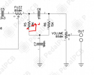
As far as the mid control 20K pot mod on the Friendly Fire, is this what would need to happen, connecting lug 2 and 3together? Or something else?

Screenshot 2021-08-01 002237.png
 
I think you've talked me into the Companion Fuzz, I can see how it will work for what I want to do. The LPF circuit I posted is a 9v variant of the Korg MS20 resonant LPF that is nice and squelchy, so they should combine in the way I'm hoping.

As far as the mid control 20K pot mod on the Friendly Fire, is this what would need to happen, connecting lug 2 and 3together? Or something else?

View attachment 14303
The MS20 filter is a fantastic choice!
you’ve got it exactly right as far as the 20k pot goes. Since it’s a linear pot, whether you connect 2 and 3 together or 1 and 2 together just depends on which way you want the pot to operate— if you take the resistance between 1 and 2 (2 and 3 tied together), it’ll be more flat fully counter-clockwise, and super scooped fully clockwise, with the stock, semi-scooped sounding value at noon. If you take the resistance between 2 and 3 (1 and 2 tied together) it’ll just be switched in direction, with a heavy scoop at full CCW, and regaining mids as you turn clockwise. Just a matter of if you want it to be seen as a ‘mids’ knob, or a ‘scoop’ control.
 
If you take the resistance between 2 and 3 (1 and 2 tied together) it’ll just be switched in direction, with a heavy scoop at full CCW, and regaining mids as you turn clockwise. Just a matter of if you want it to be seen as a ‘mids’ knob, or a ‘scoop’ control.
Mids control makes more sense to me, so I need to join lugs 1 & 2 rather than how I drew it. Thanks so much for your input on this!
 
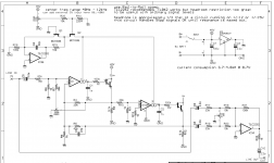
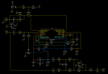
So I've whipped up a schematic of the Eric Archer Resonant Lowpass (I'm calling it EARL for now) in DipTrace because I will get a PCB fabricated for this if I'm building a prototype. I am not sure if I've interpreted the original schematic properly though. In particular, I'm unsure about IC1, especially the relationship between pin 1 and 5. I'm not sure if they are joined or if those circles between them are to indicate separation. I also don't know where V+ is coming from in the Pin7/8 region further along. To complicate matters, the component available to me through the Mouser ecad Library is vastly different to the layout of the original, so I'm hoping I've replicated it faithfully given the differences. Can anyone see any massive problems? What's going on with Pins 1&5, as well as Pins 16&12? Are 7, 8, 9, 10, 11 that look like transistors in the diagram all internal circuitry within IC1? Thanks for any help you can give.

The top image is the original schematic, then my DipTrace effort is below.

Eric Archer DIY LPF.png

EARL.png

Edit: I haven't forgotten the power section, it's just off-screen =)
 
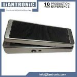
I've made some progress with this project lately. I'm going to try a Liantronic wah enclosure, I think they might be the same ones Smallbear had in stock previously. It looks like you can purchase individual units straight from the factory so I'm going to give it a go. Unfortunately, they won't give me a price for powder-coating unless I want to buy 200 units! But I'd prefer to stay married, so that won't be happening :LOL:

download.jpg

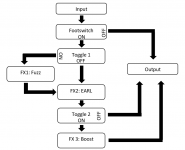
I've made a PCB design for an LPB-1 to go on the tail end of the effect as I've heard the Companion Fuzz (Friendly Fire) is generally quieter than the bypassed signal. The main question for me to think through now is how to go about wiring up the effect and the 3 PCBs that will be inside the shell. The behaviour I want is for the toe-press 3PDT switch to toggle between bypass and the EARL effect. Then I want mini-toggles on the side of the enclosure that turn the fuzz and boost on and off - but they must be bypassed when the EARL is bypassed. The effect order needs to be Fuzz > EARL > Boost to sound correct, so I'm not sure yet how to accomplish my goal.

I've drawn this flow chart for how I want it to operate but am not sure yet whether it's actually possible 🤔
Wiring concept.png
Any suggestions or input would be most welcome 🙏
 
Looks good, I think it's totally doable.

If I were drawing the flow chart, I'd need to have the end of the signal chain going back through the master-bypass footswitch — that's just how my brain needs to see it — like how on a schematic a dual-gang pot can look like two separate pots on different parts of the circuit.

Doesn't matter, I know that the fuzz-earl-boost (FEB) goes through the master bypass as a unit. Within the FEB, is the additional control to engage/bypass the various elements that compose the FEB, which makes me want to ask:


At any time are you going to use...
- just the fuzz;
- just the EARL;
- just the boost;
- just the EARL and boost together, ever?

If the boost is only to be used when the fuzz is engaged, the boost could go right after the fuzz (I know you said it needs to go after to sound correct, but...). Even though the EARL will react differently than when the boost is after it, it might sound good. Breadboard it and play a bass through both boost-placement options.


If the boost is only ever on when the fuzz is engaged, yet you still want to retain the pedal order F>E>B , you could simplify the switching for the pair with a single 4PDT-toggle.

BOOST ALTERNATIVES
I'd also look at boost alternatives, such as a MOSFET boost — the LPB-1 can introduce its own dirt into proceedings (here's a GGG PDF about it). The AMZ MOSFET Boost still has a low parts count, and even though it's fine for bass as is, you could tweak it further into a Catalinbread Sagrado Poblano Picoso bass boost. There are other boosts that might be compact enough and sound good. MXR Micro Amp can be quite compact for an op-amp boost.

You may decide the LPB-1 is still suitable/preferable for this project, but since the pedal is meant for bass I'd suggest building the LPB-1 as an EHX Mole/Hog's-Foot (LPB-1 with mods for better bass retention).


Good to see some progress. 🤙
 
Thanks @Feral Feline for these ideas. I'm concerned about the potential for extra dirt from the LPB-1. I will have a rummage for the Catalinbread SPP schematic and see whether that's an option instead.

The reason I've placed Boost last is my concern about the potential lack of headroom in the EARL. It is a circuit that has 1/3 of the headroom at 9v that it has at 12v and I'm already running a Fuzz into it. I was hoping not to mess with the voltage unless I have to, so I decided not to push it with a boost as well.

I talked to the client today and he wants simplified switching, basically on and off. I might try and still make the boost switchable, to take it out of the signal chain when not required (e.g. studio use, these guys record a bit: Foreign Films - Spotify)

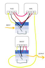
Would something like this work? Excuse the low quality diagram:
1629109778387.png
Thanks so much for the feedback and advice, as a mere guitarist it is really helpful to have bass-savy people to discuss this with.

Edit: Oops, switch 1 is supposed to have an output for bypass 😅
 
Last edited:
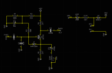
Catalinbread SPP schematic (made from Mosfet boost schematic with two value changes):
1629113875703.png
Going to sort out a PCB layout next.
 
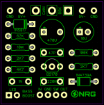
And now I've got that done:
1629117584673.png
Nice little board that, easy to route too 😅

Should I have put some filtering in the power section? I have it in most of my schematics but I didn't think to add it to this one.

Edit: Don't think that's the right package for a 220N box cap, I will update it.
 
Last edited:
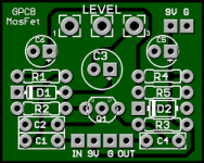
I would think having a global power-filter for the pedal is sufficient, one power-jack supplying all three circuits. If you want to have this board as a stand-alone or to add to other effects, it wouldn't hurt to add the power filtering (you can always leave it out in multi-builds), you've got enough room if you shove a few bits around. For the hell of it, here's GPCB's layout:

1629124592605.png


Re headroom of the EARL ... unless the EARL's own distortion is particularly ugly I don't think it's a concern if it distorts or not given you'll be hard-pressed to hear the EARL's distortion in conjunction with the Companion Fuzz. It would be a concern if it were fed a clean signal. Again, though, EARL's might not be a pleasant distortion. Maybe @Bricksnbeatles has some more low-down on that issue.


Also, if the Fuzz and EARL are always used together you don't need to connect both board's LEDs ("S" on your diagram), one or other would do.

There's lots of boosts out there (I've compiled a list of just the ones I'm interested in, and it's far too big to include here), but I think the SPP is a great way to go for this project.

Engaging the boost: Are you going to have a soft-switch on the side of the pedal the client can tickle with his toe? A soft-relay switch on the treadle? Easiest to have multiple footswitches if you're building it as normal Hammond enclosure with an expression-pedal jack, but if you're going with a standard wah-shell, multiple footswitches need some creative rethinking — also, client's prefs? What if you put a soft-switch on the side of the enclosure, but it's the wrong side for how/where the client puts his wah on his pedalboard?

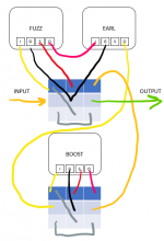
For your switching diagram, in accordance with your wanting the boost to be separate, the output of the EARL should go to lug 7 of the top switch and in turn lug 8 would take the signal to lug 2 of the lower switch.

According to what your client wants, one switch, while still having the boost as a toggle option within:
As per your diagram, the EARL exits to the Boost Sw Lug2, except the output of the boost switch should go to the master sw's lug 7 and master switch lug 8 (as you noticed) to output jack.

Oh, and you've got 1n for C1 in your SPP schematic, but it should be 10n.
Incidentally, the Blue Dragon is an AMZ/SPP boost variant with 100n input and 3u output!
 
Listening to that Radiohead bass sound, all I can think of is a Moog Ladder Filter. It has that softly-grainy saturation and a sweep of the cutoff frequency knob with a bit of resonance to help it cut through the mix. I have the Kassutronics Ladder Filter on my breadboard right now and I absolutely LOVE it. Add a gain stage to get the signal level up to 2-4Vpeak and you'll be easily overdriving the filter.

Right now I have an envelope filter circuit hooked up to the attenuverter input so it can do either positive or negative sweeps of the cutoff frequency. I can't remember offhand which circuit that is, but it has pretty simple Attack & Release controls that can be dialed in to get a similar response to that bassline.

The circuit requires +-12V, but it took maybe 10 components and a LT1054 to generate from standard +9VDC wallwart.
 
Listening to that Radiohead bass sound, all I can think of is a Moog Ladder Filter. It has that softly-grainy saturation and a sweep of the cutoff frequency knob with a bit of resonance to help it cut through the mix. I have the Kassutronics Ladder Filter on my breadboard right now and I absolutely LOVE it. Add a gain stage to get the signal level up to 2-4Vpeak and you'll be easily overdriving the filter.
Thanks for sharing that link! I'm already working on the Eric Archer Resonant LPF circuit, but I'll give the ladder filter circuit a spin if I can't get the sound I want from the EARL.
 
Also, if the Fuzz and EARL are always used together you don't need to connect both board's LEDs ("S" on your diagram), one or other would do.
🤦‍♂️😂 Thanks for noticing that haha.

Engaging the boost: Are you going to have a soft-switch on the side of the pedal the client can tickle with his toe? A soft-relay switch on the treadle? Easiest to have multiple footswitches if you're building it as normal Hammond enclosure with an expression-pedal jack, but if you're going with a standard wah-shell, multiple footswitches need some creative rethinking — also, client's prefs? What if you put a soft-switch on the side of the enclosure, but it's the wrong side for how/where the client puts his wah on his pedalboard?
I suggested a normal Hammond box with an expression pedal but it's not what is wanted by the client. I am not thinking of live adjustment for the boost during a gig. It is set and forget, with only the main bypass being operated during their performance. That's less tweakable/flexible and so not the way I would approach it, but it's also less tap-dancing for the player.

According to what your client wants, one switch, while still having the boost as a toggle option within:
As per your diagram, the EARL exits to the Boost Sw Lug2, except the output of the boost switch should go to the master sw's lug 7 and master switch lug 8 (as you noticed) to output jack.
Does this look right?
If I have my head around it, when the main switch is bypassed, no boards are in the signal path. When it is activated, Fuzz and EARL are ON, and Boost can be toggled to ON or BYPASS. That should work.

1629175784086.png

Oh, and you've got 1n for C1 in your SPP schematic, but it should be 10n.
Thanks, that was the value in the AMZ schematic I saw. I haven't actually seen an SPP schematic yet, I only saw an Effects Layout post that mentioned 2 value changes. I will update my schematic and board to the 10N value.

Thanks again for being a legend and helping me out!
 
Does this look right?
If I have my head around it, when the main switch is bypassed, no boards are in the signal path. When it is activated, Fuzz and EARL are ON, and Boost can be toggled to ON or BYPASS. That should work.

View attachment 14942
That’s exactly how I would do it! Also I wouldn’t worry about overloading the filter, as it shouldn’t be noticeable with the fuzz, and even if it was, those kinds of filter often have a nice kind of breakup to them that wouldn’t sound bad at all
 
Back
Top