Ideas needed for bass guitar filter/distortion pedal effect

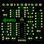
Moar progress! EARL board laid out and routed. It might not be the prettiest and is by no means perfect, but this is about the 5th go I've had at laying out this PCB and by far the best job I've done of it. Fingers crossed it passes the testing phase.
1629291478359.png
Next step is a final BOM and then ordering boards and components.
 
Update: I have finally received delivery of a wah shell. Anyone ever polished aluminium before? I think I'd like to make it shiny.

No pics atm but the boards are populated and ready to be wired up once the enclosure is ready.
 
Finally back on this project. I've got all the parts, just need to work out where to place everything. If I was doing this again, I'd now lay it all out on one PCB, but I didn't have the skill at the time. I was thinking 3M sticky foam pads for keeping the boards in place, reckon that will work ok? This thing is going to be a rat's nest of wires, reckon I'll need to do some cable management inside. Any suggestions?

IMG_20220108_135310__01.jpg
 
Latest updates:
  • Holes are drilled (9 of them!)
  • Appropriate washers found for the hole on which I accidentally went a step too far with the stepped bit 🤬
  • Most off-board components mounted
  • Shell wet sanded with 120, 240, 600 and 1200 grit
  • 9mm pots are soldered onto stripboard for alignment and easy off-board wiring
  • Boards have all ICs and transistors in their sockets
  • I found my missing 2SC536 transistors for the fuzz 😅
  • Wires are grouped and cut for 2 of the effect boards
Pics:
IMG_20220118_221703_copy_1728x3456.jpg
IMG_20220118_221850_copy_3456x1728.jpg
I'm hoping to get this built and tested in the next couple of days.
 
For those interested, here's a quick phone clip from testing: Custom bass effect

There are a couple of kinks to work out with the output jack, which only works when half removed, and the boost circuit isn't working at this stage.

The volume control on the fuzz is pretty useless, if I were doing this again I would use an internal trimmer set to maximum output rather than an external knob.
Oh wow, very cool.
 
So this pedal/science project came back to me from the band who have been using it, for some TLC. Fuzz, Boost, and switching all work fine. The Filter circuit passes audio but does not filter anymore. Also there's an occasional weird sensation like the sound is fading out, but it's brief and then returns to full power. Visual inspection doesn't reveal any obvious problems, so I got out my audio probe and began working back from the output.

Would you expect audio between R5, R12, C6 and IC1 Pin 8 on this schematic? I have sound at IC1 Pin 4 but nothing on the right side of R5/C3 or left of C6. I get continuity on the multimeter between all of these points, making me think there's a dodgy component here.

Eric Archer DIY LPF.png
 
Last edited:
Back
Top