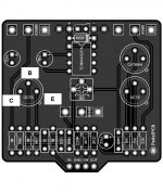
Kilimanjaro Fuzz Questions

joelorigo

Well-known member
I ordered the Kilimanjaro Fuzz PCB over the weekend. I haven't been to picky about the type of parts I have used but I was wondering since this is such a small number of parts an apparently such a finicky circuit, should I try to use more upgraded parts or maybe what they had available back in the 60's? I have been using metal film resistors and various film caps.

The doc says 2 OC75 transistors and one CV7004 but in this circuit is it more about the gain and leakage than the specific transistor?

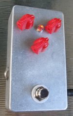
EDIT: Do regular size chicken head knobs fit on the Tayda 3-hole PedalPCB pre-drileld enclosures without bumping in to each other?
 
Last edited:
Q1 & Q3 are leakage biased, so getting the leakage right is important. Buying the specified parts numbers does not guarantee that the leakage will be right. Use sockets. If Q1's emitter ends up between 2 and 7V, you're good. The bias trim only affects Q2. Adjust the bias trim to get the desired range on the FUZZ control. Q3's bias is a matter of personal taste.

If you want it to be noisy, then by all means, use carbon comp resistors and ceramic caps. If you use good parts, you will not regret it. I'm not suggesting you spend $20 ea on paper-in oil caps.

Regular Chicken Heads will not fit. The minimum hole spacing is 1.19"; Chicken Heads are 1.24" from stem to stern. The Mini Chicken Heads that SB sells will fit. NB: this is not a Tayda predrilled box, but the pot hole spacing is the same.
Hybrid Tone Bender on a Quarantine board - front (unpainted) 02.jpg
 
Great! Thanks for the parts info. I have parts ready to order at Small Bear and Tayda.

As far as the Ge transistors, what kind of gain and leakage is ideal? From what I've beed reading, very leaky. (I just ready your FZ-1 post)

And you say "Q3's bias is a matter of personal taste." I have only built one other Ge fuzz, the Sunflower, and I did use the internal trimmer to bias that. If on the Kilimanjaro the trimmer only effects Q2, how do you bias Q3? Do you mean trying different transistors? As in this process:

Q1: Look for a transistor that the emitter is 2-7v
Q2: Use internal trimmer and fuzz knob to get desired range
Q3: Try various transistors and decide by ear
 
I don't know how many PNP Germanium transistors you have. More is better. A dozen is a good start.
Of the three transistors that end up in your Kilimanjaro, Q3 will be the leakiest, followed by Q1. Q2 will be the lowest leakage of the bunch. I'd say the lower the leakage on Q2, the better because R4 supplies plenty of base current. I had difficulty finding PNP transistors that were leaky enough to use for Q3. I ended up building an NPN version because I had NPNs with the right leakage.

Start by selecting Q3 for a collector voltage somewhere between 3V and 6V. If you can't find one that's leaky enough (collector voltage too high), then it's ok to increase R8 to bring down Q3'a collector voltage.
Next, pick Q1. Should not be too difficult to find one that works.
Finally, pick Q2. The FUZZ control is mainly a bias control. It varies the gain by throttling Q2's collector current, but it also changes the voicing. One end of the bias trim range will kill the signal, you want to be away from that end. Find a bias setting where the FUZZ control has the best range of gain and tone. In reality, you'll end up running FUZZ at or near 5:00 anyway.

This pedal is very temperature sensitive, so don't surprised if it sounds different on different days.
 
I don't have many PNP Germanium transistors right now. I'm going to start to acquire some.

Would getting something to test transistors for gain and leakage help this process?
 
I put one of the soldered ones and a us power supply in my ebay cart. Is the plastic shell important?
 
I think it is.
I got one and it worked briefly, but before I could use it in earnest it got bricked. Not even sure how I bricked it.

Makes a great paperweight now to hold down schematics I've printed out.
 
I recommend using the plastic shell. Had no trouble with mine. Full disclosure: The seller I used on eBay is no longer there, at least not under the same name. The link I gave you is for the same item from a different seller. Caveat emptor.
 
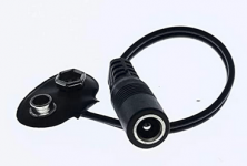
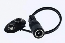
Looks ok, probably has the same stuff inside as the one I pointed out. One thing I don't like is the lack of a DC power connector. Easily remedied with one of these IF you can find one with the right polarity:

1621562230821.png
 
Looks ok, probably has the same stuff inside as the one I pointed out. One thing I don't like is the lack of a DC power connector. Easily remedied with one of these IF you can find one with the right polarity:

View attachment 12033
I have a couple of things that look like that. One came with the Voodoo Lab Pedal Power 2 + and one came with the Godlyke Power all. Would those work?
 
You asked about whether your Voodoo Lab Pedal Power 2 + would work for powering a transistor using an unidentified adapter.

I told you in general terms what you need to before you plug the power supply and adapter into the transistor tester.
 
Sorry, I meant just to ask if the adaptor that came with the Pedal Power 2 + would work for one in the photo you were showing above:
1621642471313.png

And you were suggesting that adaptor to power the transistor tester I linked on Amazon, instead of the battery that comes with it, right?

However I just realized that the one that came with the Voodoo Lab is probably battery snap to a male end, not female.
 
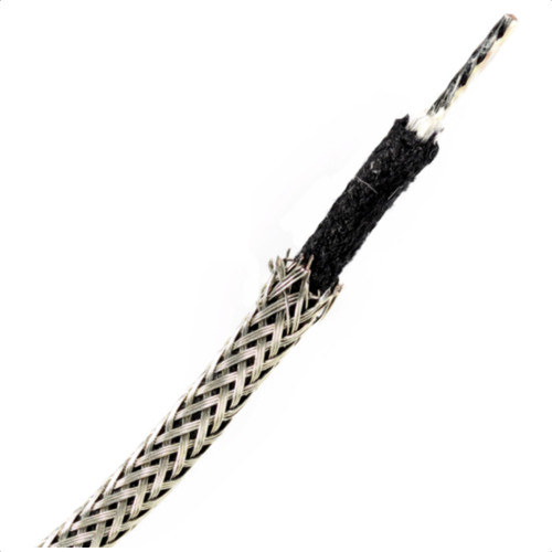
On another website's discussion about building the Tone Bender mk I, it was suggested to use "shielded wire on the in/out to the board and the in/out to the jacks - absolutely makes a big difference." Is that a good idea? If so, I have this handy:
 
I have this thing finally wired up and going to try some transistors. A question about the transistor pinout on the PCB. Do I have this correct?
 

Attachments

  • Kilimanjaro.jpg
    Kilimanjaro.jpg
    184.8 KB · Views: 8
Back
Top