
PangeaDestructor
Active member
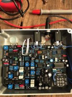
I've been working on this one for a while, finally got it all populated and wired up. At first I was getting feedback only and a dim bypass led, but adding a ground link between the breakout board and the pcb fixed both. I ripped off the power input ground pad by accident but luckily there are a few extra ground pads, so I stuck that one up top. So now I get a clean bypass signal, and a clean signal when the circuit is engaged, but there's no effect at all. I need to get a better multimeter with frequency, my cheapo AstroAI AM33d doesn't have that, so recommendations for a budget-friendly one with freq is appreciated.
Build guide here, no schematic available (confirmed with LFX they aren't able to share as part of their deal with the creator): https://lectric-fx.com/wp-content/uploads/2020/07/DC-Echo.pdf
When I dime the blend pot, the signal dies completely, if i dial it back a hair the signal returns. When I plug in the unit, I get a blip of the overload led, but then it does nothing regardless of input, and I'm reading 14-15v on both legs of that led, so i'm thinking there's something to that, but it seems like even if i had put it in backwards that shouldn't be happening or affecting the circuit.
q1 has ~13.6v going in and 0 coming out, which is correct. IC voltages look good except ic3 i'm getting 7.8v for pins 2,3 and 6 instead of the 5.6v I should have, seems like that will be corrected with a trimmer in biasing.
Pic attached, I'm flying a little blind here without a schematic, but any help would be much appreciated. This is by far the most complex build I've done, and although I've got a few dozen under my belt now I'm still a newb when it comes to circuitry.
Edit: to add, I did sub a tl072 for the 4558 at ic2. i don't see why that would matter especially since it's got the correct voltage, but just in case.
Attachments
Last edited:


")