SOLVED LED BEZEL - Pro-10: Green side not working when boxed

Ok, this one is giving me a run for my money. I built one of these already and it worked right out of the gate, with one minor issue on the green side where the LED would stay very dimly lit when bypassed. I got that issue resolved (somehow, not sure exactly), and moved on to building my second and third Pro-10s as part of a build project I’m working on. This one is build #2, and the green side is once again having issues.

The first issue arose when I attempted to add the Trimmit boards for the CLRs. The blue side went fine, but the green side did not. Long story short, I ended up breaking off a socket, along with the solder pad, which pulled up the trace, so I had to cut it. According to the trace on the board, it appeared that adding a jumper wire from the + pad to the CLR would be the fix. I did this, and it worked to get the LED to turn on when switched, but I got nothing when testing. However, the blue side worked perfectly fine. When bypassing the green side, the blue side worked as normal.

It took me a while, but I finally realized that the circuit wasn’t getting any power beyond the LED, and then it hit me: the solder pad broke off, so there was no connection to R129 (22R) in the power section, therefore no power to the green side circuit. When I had it unboxed, I then placed a jumper from the CLR to R22 on the green side, and everything worked. Yay! So, to make the fix, I removed C300 (100uF) to place a new one in to utilize the long positive lead. I then placed some shrink on the lead, positioned it across the CLR pin and 22R, and soldered in place. Not the cleanest fix, but it worked, and I tested once again before boxing.

But my excitement was short lived. I boxed the unit up, went to test it, and when I engaged the green side: only noise. I can only describe it as high-pitched whirling. I then pulled everything back out thinking something weird went on when I boxed it, tested it, and it worked perfectly fine. I then re-boxed it, tested it, and again, whirling noise. I bypassed the green side and it worked, engaged the blue side and it worked, but when engaging the green side, nothing but noise.

I then unboxed the unit again, tested, and it worked, so I figured it was a grounding issue. I then tested it with just the output jack connected to the enclosure, and there lies the issue. When the output jack is secured to the enclosure, the green side does not work.

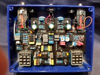
Can anyone pinpoint what might be going on? I will attach pictures of the build, as well as a screenshot of the initial trace that was broken, and how it was eventually rectified. I’m probably missing something obvious here, but I’m in galaxy brain mode after troubleshooting for a couple hours on this already.

IMG_5734.jpeg
IMG_5684.jpeg
IMG_5687.jpeg
IMG_5732.jpeg
IMG_5730.jpeg
 
My guess is that something is making a connection to ground that shouldn’t be. If you have a multi meter I would poke around in the repair you made and see that it all connects to itself but not to ground. From there I would look T the switch and make sure none of the wires coming from the backside are touching anywhere they shouldn’t be. Other than that you could connect one side of your multimeter to the output connection and see if it’s making contact somewhere it shouldn’t. Some pictures of the back of the board on the output side might be helpful.

For the repair the soldering looks cold. If you can’t identify the problem somewhere else you might try redoing that repair. Solid core wire or component legs might make a cleaner repair.
 
+1 for @DailyDovetails . Anomalies which occur after 'boxing up' are typically 'fit' problems. I've been working on amps and music effects since the late 1970's and it still occasionally happens to me. These are typically components accidentally shorting, or the obstruction bending the PCB and trace to create an open (no continuity).

Troubleshooting technique:
- Hook everything up to a test amp and send a signal into the green side (there are phone signal generator apps which along with a 1/8" to 1/4" male-male or male-female 1/4" adapter plug, which works great - or have someone playing guitar while you troubleshoot).
- Loosen parts one item at a time and begin slowly removing it until the effect comes back to life. Since your Blue side works, you can skip the output, input and DC jacks and any other common components. I'd personally start with the main PCB. I've also found stomp switches to be troublesome.
- Once the effect begins working again, lightly apply pressure on isolated parts of the PCB until you hear the function cut out. When you find it, use your sense of touch, hearing and sight to guess where it may be. The goal is to isolate the offending contact location.

My suspicion is you are using jumper wire that is too big of gauge and coupled with the shrink wrap, is coming in contact with the back of that A50K pot. I use 28AWG lead wire and it appears you are using 20AWG or 22AWG lead wire, which IMHO is electrically unnecessary and makes building cumbersome. If this is the case, try repurposing a piece of resistor lead that you trimmed off during the build, as a jumper and skip the shrink wrap. Instead, cover it with a small piece of electrical or paper masking tape.

I hope this helps and am interested in what you find.
 
My guess is that something is making a connection to ground that shouldn’t be. If you have a multi meter I would poke around in the repair you made and see that it all connects to itself but not to ground. From there I would look T the switch and make sure none of the wires coming from the backside are touching anywhere they shouldn’t be. Other than that you could connect one side of your multimeter to the output connection and see if it’s making contact somewhere it shouldn’t. Some pictures of the back of the board on the output side might be helpful.

For the repair the soldering looks cold. If you can’t identify the problem somewhere else you might try redoing that repair. Solid core wire or component legs might make a cleaner repair.
+1 for @DailyDovetails . Anomalies which occur after 'boxing up' are typically 'fit' problems. I've been working on amps and music effects since the late 1970's and it still occasionally happens to me. These are typically components accidentally shorting, or the obstruction bending the PCB and trace to create an open (no continuity).

Troubleshooting technique:
- Hook everything up to a test amp and send a signal into the green side (there are phone signal generator apps which along with a 1/8" to 1/4" male-male or male-female 1/4" adapter plug, which works great - or have someone playing guitar while you troubleshoot).
- Loosen parts one item at a time and begin slowly removing it until the effect comes back to life. Since your Blue side works, you can skip the output, input and DC jacks and any other common components. I'd personally start with the main PCB. I've also found stomp switches to be troublesome.
- Once the effect begins working again, lightly apply pressure on isolated parts of the PCB until you hear the function cut out. When you find it, use your sense of touch, hearing and sight to guess where it may be. The goal is to isolate the offending contact location.

My suspicion is you are using jumper wire that is too big of gauge and coupled with the shrink wrap, is coming in contact with the back of that A50K pot. I use 28AWG lead wire and it appears you are using 20AWG or 22AWG lead wire, which IMHO is electrically unnecessary and makes building cumbersome. If this is the case, try repurposing a piece of resistor lead that you trimmed off during the build, as a jumper and skip the shrink wrap. Instead, cover it with a small piece of electrical or paper masking tape.

I hope this helps and am interested in what you find.


Thank you both for the replies and advice.

@andrewsrea - It's funny that you mention this, as that is exactly what happened. I started doing more troubleshooting, and I am able to pinpoint a general location of the short, or at least I think so. Here are the steps I took:

- Unboxed board, attached output jack to enclosure, tested: worked. This, I believe, ruled out my initial theory
- Re-boxed board, mounted everything and tightened, tested: did not work
- Removed green side footswitch from enclosure, tested: worked. When I then put the footswitch back into the enclosure, it would get to a point where it would stop working, basically once the footswitch was fully in the enclosure. I did not need to tighten down the switch to create the malfunction
- Unboxed board, tested while maneuvering footswitch around, creating tension as best I could to replicate what was happening in the enclosure: worked - could not replicate malfunction
- Re-boxed board, tightened down jacks and footswitches first, tested: worked! Mind blown. Thought I had it.

- Began placing washers/nuts on each pot one at a time, starting with the blue side. As I made my way to the green side, that's where I began replicating the malfunction. I was able to tighten down one of the volume/drive pots (I forget which off the top of my head), and then moved to the tone pot. When I went to place the washer/nut on the tone pot, that is when I was able to create the malfunction, and it then completely cut out when I tightened down the nut. I removed the nut and washer, and tension eased off of the board, so it began working again. I pressed on the PCB where the IC is located above the tone pot, and it began malfunctioning. I then went from the other side and simply shifted the pot around, and was again able to create the malfunction.

That was as far as I could get in my troubleshooting for now, but it does appear that tension is creating an issue once it gets tightened down. This is a very tight build, so it doesn't surprise me all that much. As far as the repair jumper, I did not use hookup wire for that. I used the full lead of the capacitor to run directly to the resistors that needed it, it's just a crappy joint that I soldered quickly and will fix before final boxing, so it just looks a mess. The hookup wire I am using is 24 AWG pre-bond, but again, did not use that for the jumper on the repair. I also used dust caps on the pots, so they should be isolated from creating any shorts if something were to brush up against it.

Any pointers on where to go from here would be greatly appreciated, and hopefully tomorrow I can get this nailed down.
I would reflow the joints in the pot that are causing you the issue. While doing that inspect that there are no rogue globs of solder, component legs or strands of wire. From there occasionally I get a pot thats not very good. It’s also possible that a portion of the pots leg could be touching the enclosure when boxed.

You can test between legs 1 and 3 and it should read at about 25k you may or may not be able to do this in circuit. If you go from 1-2 and 2-3 you should get 0 with the pot turned one way and 25k the other. Sometimes the joints I have marked in yellow are loose and that can cause issues and sometimes I get a pot where the wiper doesn’t make contact correctly and you can get it to engage or disengage by pushing or pulling on the pots shaft.
1717869816603.jpeg
 
I would reflow the joints in the pot that are causing you the issue. While doing that inspect that there are no rogue globs of solder, component legs or strands of wire. From there occasionally I get a pot thats not very good. It’s also possible that a portion of the pots leg could be touching the enclosure when boxed.

You can test between legs 1 and 3 and it should read at about 25k you may or may not be able to do this in circuit. If you go from 1-2 and 2-3 you should get 0 with the pot turned one way and 25k the other. Sometimes the joints I have marked in yellow are loose and that can cause issues and sometimes I get a pot where the wiper doesn’t make contact correctly and you can get it to engage or disengage by pushing or pulling on the pots shaft.
View attachment 76435
This all makes sense. I will give the joints a once-over, reflow, inspect, etc. and see what happens. One thing I did notice with this pot in particular is that it sits the lowest when I attempt to box it, so it's a bit of a struggle to get the nut to catch the threads. Whatever it is, it seems to be stemming from somewhere near this pot, or the pot itself.
 
You've got the trouble shooting process down!

Two key pieces of information that I derived from your last post: the fault is replicated via the green stomp switch mounting and also by way of the green tone pot mounting. Given the proximity of the two, I am guessing the problem is in the switch leads being caused by changes in the elevation of the two PCB's when mounting, causing flexing or pressure on the lead wires. I would suggest starting there.

My Pro-Ten build, I did the switch leads a little different (pictured below). With the main PCB and the switch PBC installed into the enclosure, I soldered leftover resistor leads straight into each PCB, starting from the middle and working my way to the outer joints. This way neither board is exerting flex onto each other. These were soldered on the side pictured. This is tedious but might be worthwhile for you.

Ignore some of the differences between the stock build and my picture, as I have modified both sides of mine.
 

Attachments

  • 20230317_141123.jpg
    20230317_141123.jpg
    584.8 KB · Views: 7
You've got the trouble shooting process down!

Two key pieces of information that I derived from your last post: the fault is replicated via the green stomp switch mounting and also by way of the green tone pot mounting. Given the proximity of the two, I am guessing the problem is in the switch leads being caused by changes in the elevation of the two PCB's when mounting, causing flexing or pressure on the lead wires. I would suggest starting there.

My Pro-Ten build, I did the switch leads a little different (pictured below). With the main PCB and the switch PBC installed into the enclosure, I soldered leftover resistor leads straight into each PCB, starting from the middle and working my way to the outer joints. This way neither board is exerting flex onto each other. These were soldered on the side pictured. This is tedious but might be worthwhile for you.

Ignore some of the differences between the stock build and my picture, as I have modified both sides of mine.
Got it, I will give the switch leads a try like this in the near future.

Unfortunately, I’m going to have to table this troubleshooting process for a bit. The malfunction can only be replicated when the board is boxed and everything is tightened down, so I know something is going on when it’s all snug inside there, I just can’t pinpoint what. I have tried very hard to get it to short outside of the box to no avail, so that’s making it very frustrating to troubleshoot.

I taped off legs on the tone pot, taped off LED legs, bent the pot legs thinking maybe they were touching the enclosure, and have tried manipulating the board, applying pressure, and bending pots trying to replicate the short outside of the enclosure, but nothing is doing.

My next step will be to replace the tone pot. I tested it, and it’s reading about 17k on my multimeter, while the tone pot on the blue side is reading right about 25k. Again, I can’t get it to malfunction outside of the enclosure though, so who knows. If that doesn’t work, I will attempt to solder in the board leads with legs when everything is pre-mounted.

The weird part is, it’s a very fine line to get it to short. I had it boxed up and working for a minute with everything but the blue side switch installed. Once I installed that switch and tightened it down, nothing. I then pulled that switch back out moving it around was cutting in and out.

I will have to put this on hold though, as I’ve moved this thing in and out so many times now that wires are beginning to break in their joints, which is going to be no fun to fix. I will table this for now, clean up my bench, build something else, and come back to this soon.
 
Hmm, I've been giving this some more thought, and I'm wondering if the LED bezel could be the culprit. Since I can only get the circuit to short while it's mounted in the enclosure, it has to be something in the fit that is causing it. I'm using metal LED bezels, so they could certainly be making contact with something on the board, or one of the tone pot legs, thereby shorting the circuit. Since that is an easier troubleshooting step than removing/replacing the tone pot, I will give it a shot. Here will be my next steps:

- Rewire any broken connections
- Clean entire board with IPA/toothbrush
- Remove LED bezels from both sides
- Re-box board without LED bezels and tighten everything down to test

If malfunction does not replicate: isolate LED bezels and we're good to go
If malfunction does continue: remove and replace tone pot and go from there

This is fun!
 
Update: got a quick 10 mins to patch up some connections and remove the bezels. I re-boxed everything, tightened everything down, and tested.

It worked!

The only thing is, I’m using black painted metal bezels in this one, so the only part that is grounded with the enclosure is the nut/washer. I’m guessing that once the pots are tightened down, the nut is coming into contact with the tone pot leg.

Next step will be do isolate the nut/washer so it is not grounded, as well as tape off the pot legs for an extra measure. Will report back once I have the bezels reinstalled and get it tested.
 
Nylon washers to the rescue!

@andrewsrea and @DailyDovetails thank you for the tips, tricks, and advice. Thanks to your input, I was able to isolate the issue to a local component, which brought me to a solution. The washer/nut on my LED bezel was grounding, and was tight enough in the enclosure that it must have been making contact with the tone pot leg. I insulated the nut by using a nylon washer, and that has resolved the issue. I re-boxed, tightened everything down including pots, switches, and jacks, and we are good to go.

Glad to hear you corrected it!

IMHO, a Great pedal. I have a few mods on mine: trimmers on the Blue side to turn it into a King of Tone; a 'fat' control on the Green side to tighten up the bass when required, added a smidge more gain and changed to clipping diodes to make it a bit more amp like in its response.
Ohhh, those mods sound like something I’d be interested in. Care to explain in more detail?
 
Ohhh, those mods sound like something I’d be interested in. Care to explain in more detail?

Asking me to give up my secrets, jeeze! ;)

This is using the individual schematics for each side of the Pro-10, as I have not seen a combined schematic.

Mods for Pro-10 Blue (Marshall BB, Glory Hole, etc.):
- Kot Mod: place 25K trimmers (one per resistor) in series with R2 & R3 and insert a 50K trimmer in series with C7 at the junction of R9, R10 & C8 (as a presence control). Set the R2 & R3 trimmers for 4K7 & 3K3 resistance, respectively for 'Bluesbreaker mode.' Set R2 for 25K & R3 for 33K for 'King of Tone mode.' A variation of this mod (real estate depending) is to skip the trimmers, utilize a top side DPDT switch, and substitute a 27K for R2 and a 33K for R3. Send a lead ire from R2 to pin 1 of the DPDT, a lead from R3 to pin 6 of the DPST (or DPDT), jumper a 5K6 resistor from pin 1 of the DPST to pin 2, then jumper a 3K9 resistor from pin 6 to pin 5. Solder a lead wire from the other end of R2 to pin 2 of the DPST. Solder a lead from the other end of R3 to pin 5. If you are using a DPDT, pins 3 & 4 will have no connections. This will allow you to switch between Kot and BB on the fly, without opening the pedal.
- Play Nice Mod: Substitute the A5K 'Level' potentiometer with an A25K. Increases the output impedance, lowering the likelihood of loading the next pedal. IMHO, it also makes the roll-off of the guitar volume a little less drastic, making it easier to create some shades of grit as you back off the volume.

Mods for Pro-10 Green (or an ODR-1 derivative):
- Tight / Fat Control: Insert a C50K potentiometer between R7 and C5 (in series). Clockwise = more bass thickness inserted into the first gain stage. Fully clockwise = stock. Fully counterclockwise = 'tight' sounding.
- Higher Gain: Substitute an A250K pot for 'Gain.'
- Boost Switch: This one is really a low gain switch from the stock build. Remove one leg of R27 at point '1' (where it joins C23). Solder a lead wire to the unattached leg, sent that to a DPST switch and send the return lead wire into the solder hole '1' (where it joins C23). 'Off' will counterbalance the High Gain mod and on will boost the gain. Note that 'off' would be a stock ODR-1
- Amp-like Clipping: Socket D3 & D4. Substitute D3 (1N4148) with a 2N7000 (MOSFET). Substitute D4 with a 2N7000 + 1N5817 (Schottky diode, in series). The 2N7000 has a forward voltage like the 1N4148 but has a softer tube-like curve and the Schottky in series makes the hard clipping slightly asymmetrical (like a tube amp).
- Focus, Dynamics and Less Noise: Substitute 68pF for C24 (less input noise, with no perceived loss in presence & plays better with the 'bright' Bule side). Substitute 68nF for C1, which reduces energy-stealing frequencies below a low-E on a bass guitar (simulating a stock ODR-1's 200nF in series with a 100nF). Substitute 0.47uF for C20, which also rolls off energy stealing frequencies below fundamental notes. This makes it more 'studio' friendly, making a guitar sit better in a band mix.
 
Back
Top