LED Positioning

Working on a couple of projects that require some unusual LED placement. Usually I drill a hole in the enclosure directly above where the LED is on the circuit board, then adjust the height of the legs and solder them in place. I use the rigidity of the LED legs to poke into the LED holder when I insert the PCB into the enclosure.

However, with these projects the LEDs need to be positioned away from their location on the PCB. Just wondering how you guys do this kind of thing? Obviously I'll need to attach the LEDs to some pieces of wire to extend their reach but how then do you get them into position? Hope I've explained my question correctly! Looking forward to hearing your techniques!
 
Last edited:
Love My Switches sells these prewired (with resistor) LED's in a nice bezel for $.99 they are a pleasure to use.

Yes, those are nice, but don't fit in a 1590B enclosure, if I'm not mistaken (too long.) But since PedalPCB builds are designed around 125B enclosures, they work well (I always try to get my builds to fit in 1590B enclosures, if I can.)

One other thing to note - since they already include a CLR in the housing, you need to jumper the CLR on the PedalPCB board, or use something low like a 100 ohm resistor, otherwise the LED will be too dim.

They actually fit perfect in 1590Bs you just have to snip off the little black plastic tab where the wires come out. I just built an etched EQD Bellows in a 1590B with one! Also, I usually just run the power back to the DC jack because the leads on those prewired LEDs are long enough to reach the back.
 
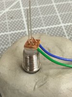
When I am in situations where the LED is not supported directly by the board, I pre-wire the LED, heat-shrink the solder joints and use a tiny drop of the thick crazy glue to keep the LED in place. A 3mm LED fits nicely in a 1/8" hole.
 
Thanks for everyone's suggestions! I actually have a tonne of those bezels, but I've always used them when the LED is supported by the board. I didn't think those plug things would actually keep the LED in place. I'm going to give that a go later today, if that fails I'll try the superglue thing. I'll report back, thanks again :)
 
They actually fit perfect in 1590Bs you just have to snip off the little black plastic tab where the wires come out. I just built an etched EQD Bellows in a 1590B with one! Also, I usually just run the power back to the DC jack because the leads on those prewired LEDs are long enough to reach the back.
Do you run red wire to dc jack + and black wire to SW on the board with jumpers A-K and 4k7 as a jumper or can I just leave A-K empty? Board currently has a 4k7 installed but want to use the prewired love my switches LED... was thinking to leave A and K blank open and go red to + DC and black to SW on pcb, but not sure if it’ll work.
 
Do you run red wire to dc jack + and black wire to SW on the board with jumpers A-K and 4k7 as a jumper or can I just leave A-K empty? Board currently has a 4k7 installed but want to use the prewired love my switches LED... was thinking to leave A and K blank open and go red to + DC and black to SW on pcb, but not sure if it’ll work.
Or can I just wire it to the dc jack and leave A-K blank, no wire and leave 4k7 installed on the pcb as it currently is?
 
If you have room you could use a larger piece of vero and add the resistor
I have an LED housing with a resistor in it already with an anode and cathode line. In your Vero board example that is similar, where would you connect those lines to a standard pedal pcb board if the board already has the 4K7 installed? I was thinking I could connect the lines to A-K and run a lead in parallel with the pcb resistor to bypass it but was wondering if there was an easier way, ie DC jack and SW?
 
I have an LED housing with a resistor in it already with an anode and cathode line. In your Vero board example that is similar, where would you connect those lines to a standard pedal pcb board if the board already has the 4K7 installed? I was thinking I could connect the lines to A-K and run a lead in parallel with the pcb resistor to bypass it but was wondering if there was an easier way, ie DC jack and SW?
You could do either
 
Depends on how the PCB is routed. Some have the resistor on the anode side and some have it on the cathode side. Check the schematic.

NB: any time you deviate from the Build Docs, reviewing the schematic helps avoid unpleasant surprises.
 
Back
Top