Over the weekend I had a few hours and was super excited to work on this a bit more. Here's where I stand.
The enclosure has been painted and mounted on the board. It's screwed in to the top hardboard only. I realized the other day I would have to do it this way since there will be multiple wires coming in/out of the module. A few minutes measuring and a few minutes more with a jigsaw/hand drill and BAM. Hole is cut out. Then came the task of drilling the holes correctly so I can mount the screws into the enclosure and through the hardboard. The end goal for this project is to be able to (assuming for troubleshooting or disassembly only) remove the top hardboard piece to get at any of the guts. So,, the datasheets provided me the measurements I needed to drill out the screw holes and I was pretty darned close. Not perfect, but good enough. Now you know why in a previous post I mentioned I have a spare 1590BB lid.
I'm still waiting on some binding posts to come in the mail. Once those are installed (one for ground and one for audio probe) I think the main board will be done. Then I need to start hooking up the robot porn inside the enclosure.
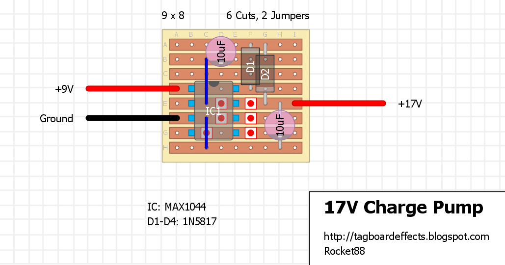
I had an idea regarding the charge pump. The stripboard layout has 3 different layouts: 18v, 25v, and 33v. Using the same chip (MAX1044) you can also get -9V. I'll have to breadboard this to see if I can get everything at once and install a rotary switch to select the voltage. I have a "garbage" 1590A that was drilled incorrectly for the in/out jacks that I may salvage and put the charge pump in there.
Collection of vero (stripboard) & tagboard layouts for 100s of popular guitar effects, with over 500 verified designs. DIY your own boutique effects!
tagboardeffects.blogspot.com
The MAX1044 is a sensitive chip that can't take more than 10v. To counter than I'll have to add a faux voltage regulator with a zener diode. I wrote about it in my circuit design thread. Once I put my thoughts down to keyboard it makes a lot more sense now. I'll have to design a layout once I confirm the circuit does what I want.
A lot of the guys here, including Robert, use DIPtrace. There is a free version for non-commercial used. I've fooled around with it a bit, but since there are others here who are already good at it, I usually defer to them. Fig knows where to order boards. DIPtrace you say.....Im going to...
forum.pedalpcb.com
This then leaves the question if there's enough real estate for a second voltage indicator. The short answer is yes, but I may need to adjust the wiring underneath a bit.
2 other goodies are thrown on here just for the nice picture, but one of them may have a more permanent place on this board. Wiring is still a mess, but that's because nothing's hooked up yet. I'd rather trim down some wires than extend them..
A lot of the guys here, including Robert, use DIPtrace. There is a free version for non-commercial used. I've fooled around with it a bit, but since there are others here who are already good at it, I usually defer to them. Fig knows where to order boards. DIPtrace you say.....Im going to...
More and more I like stripboard because I am always wanting to try different ideas and fit them into a 1590B! PCBs are a luxury and make building something you know you will like easily, reliably and quickly. And to me Vero/stripboard is kind of the next step for those of us who want to take...
forum.pedalpcb.com
OK, step one of this mini project is done. Step 2: make a box for it. Hmm... a 1590A will take up too much real estate on the board. This leaves me with 2 options: find a small plastic enclosure to put this in or make one out of some scrap wood. I chose the scrap wood approach. I found a small sheet of 1/4" plywood in my garage and cut it to size. I'm also going to put a rotary switch to toggle between 9v, -9v, 17v, and 25v. A dry fit with some masking tape looks pretty good to me. I'll probably need to reinforce the butt joint so it doesn't break, but if this gets dropped when it's on the final project I think I've got bigger problems.... The enclosure is about 3"x1.25"x1"
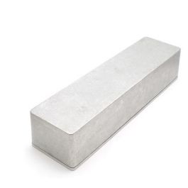
I'm having a dilemma. Usually about halfway through a jerry rigged project I have a moment of panic. Why? Because it's usually at about this point that I realize that I can do things differently in possibly a better way. I keep looking at the above pictures with all the components in a "dry fit", small boxes I'm making, etc. and I realize I'm wasting a lot of real estate space. Is it possible to put nearly everything I want into one enclosure. Behold the 1032L
Tayda Electronics - Get It Fast - Same Day Shipping
www.taydaelectronics.com
I think this will fit everything I need into one enclosure (audio probe, step up/down, bypass switch, power selector switch, etc.) and is basically the size of (2) 125b enclosures lined up. What's the drawback? It's a half inch higher than a 125b and I found a 125b to be a bit too tall on this rig. This would mean the thickest part of this platform would be 3 inches plus tall!! Plus, it may block some of the light coming from my bench onto the breadboard itself. Besides fitting everything into one unit, it will also save me real estate on the platform itself for my other goodies like a component tester, substitution box, and pot mounting terminal blocks. Do you see my dilemma now?
So, do I keep going with my original design or start fresh with a new layout? The only extra cost at this point would be for the 1032L enclosure.
The 1032L enclosure is the way to go for this project. @fig had an extra one laying around and is donating to the cause! Thanks fig!
It’s time for a complete redesign with one of the last scrap plywood piece I have left.
Here’s a preview of what it will look like. I’m toying with the idea of a wave generator (sine, sawtooth, and square with frequency knob) and it may be an add on further down the road. Those are what the switches and knobs in the very middle are. When I get some more time in front of an actual keyboard I’ll do a better write up of what does what.
So, I stared at the above picture for quite a while last night. In my head I was saying "THIS should go here instead. THAT should go there...". Which means I adjusted the layout this morning. Here's where I stand. I will explain what switch does what starting from the left.
I should mention that the stomp switches you see are placeholders until I get some toggle 3pdt in my next Tayda order (still waiting for it to hit the US), but the footprint should be the same.
All the way on the left is a 3pdt to select which power supply is the "active" one. If you look above I have terminals and a regular DC jack. The switch controls which one I want to use. The third pole is for a LED indicator telling me which one is active/on. The dpdt next to it throws the power to the rails (I think ground will always be "active" on the board instead of severing the connection). THe next 3 controls are all related to the right power rail for the breadboard. THe middle dpdt will select whether I want to step down or step up the voltage. The left knob is the step down section and the right rotary is for the step up section. The two switches you see in the middle are for the test probe. The 3pdt will sever the connections to the audio output and the right LED meter and throw them to the dpdt before the empty space. THAT switch will control whether I want the probe to test audio or voltage and will have a LED indicator.
All the way on the right is signal active/bypass with LED telling me which one. This was a needed upgrade from the protoboard itself.
That empty section toward the right is for a potential signal/wave generator to act as audio input for testing. I say potential since I still need to test a few schematics and see how they work with my speaker and simple breadboard fuzzes, boosters, etc. I'll need a small rotary switch to complete it, but that may be a future Tayda order.
The 2 LED meters will show how much voltage will go to each power rail on the breadboard itself. I've got extra real estate space on the platform itself, so I may throw a more permanent component tester on there. The transistor box is just to show off a goodie I have and to see how much platform space I'll need.
In the event the power test probe isn't very accurate, I will most likely install that black speaker terminal all the way on the left just for ground. I can throw the DMM lead in there and test away. The audio probe terminal on the right isn't dependent on another device to make it work since it's just a simple wire with a cap thrown on it.
While waiting for my goodies to come in the mailbox, I took the time to cut out the new board and round off the bottom edge. Don't worry, it's just the angle of the picture to potentially show the rounded corners. It's a rectangle, not a trapezoid. I also made a voltage divider through a buffer to help with the LED meter. I'll also post this in my stripboard build thread. Yes, that's a Buddy hair on the pot and was too lazy to clean it off before the pic
Still waiting on my fig care package, but took the time to cut out the holes for the LED meters and power/signal wires. The later is plugged with some plastic LED bezels. Looks cleaner, right?
Also, took a router to the main cavity for the voltage meters and signal/power wires
Painters tape applied. Switches and pots are marked. Hard to tell in the pic, but they’re there. Take a deep breath, Buddy. You got this. Time to drill…
Installed the rotary switch to the charge pump and attached the input voltages of that and the step down module to the selector switch. Not much progress, but progress nonetheless. I feel like I’m putting an amp together!
Tayda order finally came today with some switches, Bi/Tri-color LEDs, and binding posts to tack on. Geez, this is going to take longer than I thought, but I'm having fun and that's the whole point of this project.
Wire has been tacked on to the hardboard to transfer from the breadboard to main enclosure. Volt meters too. Could I get this done by new year's? I think so. I'm off from work all next week which is nice.
Since I have a bunch of vero I might as well use it. Stripboard will act for star grounding and power. There are 2 separate power rails for my platform so there are 2 strips for power, though one feeds into the other. Another row jumpers the main supply into separate CLR for the individual diodes. Could I have done it differently? Sure, but this is the route I chose.
Probe selector and half of the power selector all soldered up. This is where the REAL fun is…
Barely had any work today and finally put it all together. Robot porn coming shortly. Everything on this is functional, but not perfect.
My charge pump isn't cooperating when its in the enclosure. Tested outside the enclosure on its own it works fine. I've got my feelers out how to fix it. I'm suspecting there's loading happening on the pump and throwing off the output voltages.
I breadboarded a simple circuit and there is a noticeable amount of noise. I think the best course to fix it would be to add some shielded cable for the audio portion.
This has sat for a few days unattended (mostly due to the holiday weekend). The more I thought about this as is, the more disappointed I am. The way the power is set up I can only allow 2 separate voltages on the board at a time without additional breadboard work such as a voltage divider/regulator. The protoboard has multiple voltages to plug into at once and I think I may go with that. The charge pump and SAG control will be moved onto the platform itself to have “plug and play” abilities with some jumper wires. This frees up three holes already drilled in the enclosure. In addition, the more I thought about it the more I realize I don’t need 2 volt meters. I may just keep one for voltage testing only. What does this all mean? Another redesign…..
I need to test a few circuit ideas before committing to something to put in there.
Sigh….at least I can play around with my new soldering station.