Modifying Old Rockman Pedal for "Always On"...?...

Caldo71

Active member
Hey folks,

So if any of you recognize me and my posts from the last couple years, you my know that "my deal" has usually been figuring out ways to house pedalpcb stuff into rack-mountable enclosures. Any pedal I love goes into my rack alongside its' peers in a big rack enclosure, and is controlled by a Vodoo Labs HEX loop switching system and their accompanying floorboard. As such, I wire up these pedals as "always on" in the manner that you guys educated me on from day one.

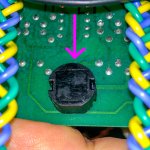
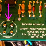
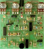
The newest addition to that family is NOT a pedalpcb build, but an ancient Rockman Acoustic Guitar Simulator pedal that I bought used on Reverb. As such, I don't have the chops to recognize how to do that same "always on" situation on this little guy: it's on/off switch is one of those "soft touch" buttons, which has four contact points on its' reverse side—see pics below...

00_Acoustic-Simulator_TOP.jpg
01_Acoustic-Simulator_BOTTOM.jpg

...I don't even know what that style of on/off switching component with only four contact points is called, actually.

I'm assuming that it's probably as simple as jumpering two of the four points on the PCB once I desolder that switch, but I just don't know which points to jumper specifically, since I don't know how those four-lead switches make the connection.

Can anyone help me out with this one? THANKS in advance....
 
It uses FET switching. A schematic is needed to suss out how the FETs are used to engage/disengage the effect. Simply jumping that switch won't work.
 
It uses FET switching. A schematic is needed to suss out how the FETs are used to engage/disengage the effect. Simply jumping that switch won't work.
Would it stand to reason then that the same issue (needing schematic to proceed further) would come into play were I to instead choose to replace that FET switch with a toggle switch?
 
That switch is just a simple push-button. It triggers a flip-flop circuit that switches a series of JFETs on or off for active/bypass modes.

You'd need to either force the flip-flip circuit on, or jumper and remove a combination of JFETs.

Send it over, I'll trace it and send it back either modified or with the information you need to modify it.
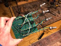
Hey @Robert and @Gordo I REALLY like where you guys are going with this (nudge, nudge)...but this particular specimen has already been 99% desoldered/resoldered by yours-truly to be racked up (see attached pics) so I think it's staying home ;-)

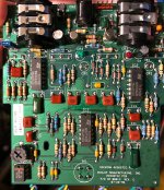
THAT SAID, these pedals are SUPER under-valued compared to the insane prices that other vintage Scholz gear is going for now, and I think it's a really great contender for you guys to mess with as a potential PCB for this site. As you can see from the pics, the component count is not too bad at all! So @Robert if you message me your mailing address, what I will do is purchase ANOTHER one on Reverb, and just send it right over to ya!

The main reason I am obsessing over this pedal right now is that it is sonically very similar to the sound of the "clean 2" setting on the X-100 and Sustainor. That sound that's all over the Hysteria album. I've been bugging people all over this forum to build that into a pedal form to little avail whilst that goofy Rockman distortion sound gets all the love and attention. So when I discovered that this circuit sounds pretty damn close (especially if you add in a compressor and a chorus holy crap) I latched on pretty hard!

IMG_1914.jpg
IMG_1915.jpg
 
Would it stand to reason then that the same issue (needing schematic to proceed further) would come into play were I to instead choose to replace that FET switch with a toggle switch?
Correct. Replacing the existing momentary switch would not work as anticipated.

I'd wager that those transistor (cans) on the PCB are likely 2N4339 JFETs. In your shoes, I'd take Robert up on his offer. In my shoes, I'd trace it and sort out how to bypass the JFET switching.
 
Correct. Replacing the existing momentary switch would not work as anticipated.

I'd wager that those transistor (cans) on the PCB are likely 2N4339 JFETs. In your shoes, I'd take Robert up on his offer. In my shoes, I'd trace it and sort out how to bypass the JFET switching.
Yep, I'm definitely sending Robert a unit!
 
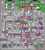
Just got in two Rockman Acoustic Pedals - an SR&D Rockman Acoustic Pedal with the gray stomp button (circa 1994); and a Dunlop version with the blue stomp button (circa 1995). I've already started tracing the SR&D version and the Dunlop version is next. I want to compare the two for what differences may be in store. This image below is mapped PCB layout diagram of the SR&D version . . . .

Rockman_Acoustic_Pedal_PCB_Mapped_Trace_01.png

Rockman_Acoustic_Pedal_PCB_Top.jpg

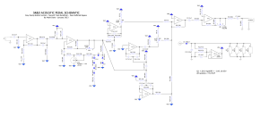
After the initial tracing is done, I'll remove the buffered bypass stuff and post the finished schematic versions.
 
Oops. CLN2 is definitely the sound I’m after so I’d be all over this project.
Yeah I did a little test in my studio before I sent it off to @Robert with a real rockmodule compressor and chorus after it, and it was pretty f&@$ing close to “that sound”.

I have a PCB of the “Woody” analog acoustic guitar emulator clone that can be had out there coming to me in the mail right now as well, and I’m wondering how that one will compare as well.

It just kinda occurs to me that for Scholz this might have been a cart-before-the-horse situation at the time. Like, he was all “hey this sounds kinda like an acoustic…”
 
Just got in two Rockman Acoustic Pedals - an SR&D Rockman Acoustic Pedal with the gray stomp button (circa 1994); and a Dunlop version with the blue stomp button (circa 1995). I've already started tracing the SR&D version and the Dunlop version is next. I want to compare the two for what differences may be in store. This image below is mapped PCB layout diagram of the SR&D version . . . .

View attachment 40407

View attachment 40408

After the initial tracing is done, I'll remove the buffered bypass stuff and post the finished schematic versions.
@Robert maybe you and @Cybercow should team up!!!
 
Back
Top