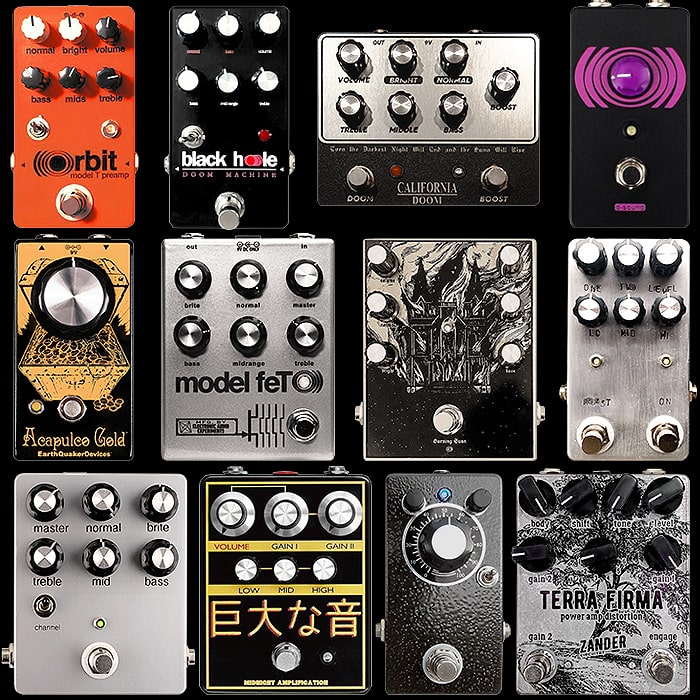
SOLVED Mofeta bass pot kinda useless?

xayk

New member
Weird little issue with a Mofeta build. Volume works, both channels work, mid and treble work, pedal overall sounds like I'd expect. But the bass control does next to nothing. I swapped out a guitar in E standard for a bass in A standard (lulz), but nothing. Assuming my damaged ears were the culprit I fired up the analyzer in Logic, which shows mid and treble responding to knob turns but not bass. "Maybe it's the interface for some reason," I assumed, but running it before an Aion Lab and/or an MP-1 didn't change anything.
IMG_7594.jpg

Bass pot (in circuit) tests as expected, going from approx. 1 meg to zero as its turned. I assumed the TMB tonestack would be similar to the schematic available from Coda, and it is (except the Mofeta leaving treble and going into power amp/saturation affair, I assume):
Screen Shot 2021-10-21 at 4.07.51 PM.png
All points have connectivity where they should and none I can test where they shouldn't, 22nf & 270pf caps and 56k resistor look to be correct, pots are correct. I checked the electrolytics to make sure I wasn't choking out frequencies before they hit the tonestack, and those are visibly correct. I certainly can replace the caps and resistors and the pot, but I guess I'm wondering if there's anything I'm missing before I do so. (Or to be prepared if/when that doesn't work.)

The fact that the entire rest of the circuit works and this one small section doesn't makes me assume it's tonestack related, but happy to hear opinions.
 
The BASS control in this type of tone stack has the most leverage when MID is turned down.

You can measure the BASS pot in-circuit with power off. When BASS is dimed, do you read 1M across pins 1 & 3?

How did you set the bias trimmers? Report the drain voltages on Q1-Q3.

Don't start swapping out parts until you know what's wrong, otherwise you risk damaging the board from repeated soldering and desoldering.
 
Thanks @Chuck D. Bones, appreciate the guidance.

Bass pot, without power, measures 1M across pins 1 and 3 with knob fully clockwise. (And close to zero counter-clockwise.)

Reading through the various Mofeta threads, I had the trimmers set around 12v for drain on Q1, Q2, and Q3. But I revisited the data sheet and, assuming the TC1044SCPA is doubling the voltage (IC100 pin 8 to D100 + 101), set the trimmers to approximately 9v. No change in the bass pot usefulness. Other threads also said 4.5v was the wave of the future, so adjusted to that but still no change to the bass pot. (Of note: Q4 is getting 17.63 on the drain, connected to pin 3 of BIAS3.)
 
Maybe C17 is not connected. Could be a bad solder joint. Time to pull the board and do some close-up visual inspection of the solder side. Did you substitute any parts?

(Of note: Q4 is getting 17.63 on the drain, connected to pin 3 of BIAS3.)

That sounds about right.
 
Update: tested and reviewed for noticeable bad/cold solder joints, touched up one or two though they still had expected connectivity. Nothing bridged visibly or connecting unexpectedly via DMM.
  • Bass pot leg 3&2 connect to Treble leg 1 and C17
  • C17 connects to C18 and R11
  • R11 connects to Q4 source and R10
  • Bass pot leg 1 connects to Mid pot leg 3
  • Mid pot leg 1 connects to ground
  • Treble leg 3 connects to C12, which connects to R10/R11/Q4 source
R10 goes to ground and is presumably the equivalent of the Coda R9, though it's 100k in the Sunn/Coda vs 3k3 in the Mofeta. After verifying, no change to the bass pot functionality.

(Also this was intended for Troubleshooting not General, mea culpa.)
Can you confirm if You have Continuity on these Matching Circles?
I maybe wrong as there is hidden traces :
Confirm R10 - 3K3 Orange, Orange, Black, Brown, Brown.
R11 - 56K Green, Blue, Black, Red, Brown.
Mofeta Continuity Test.jpg
 
Last edited:
Thanks @music6000 - your diagram is spot-on except for R11, where the circles are swapped (aqua on top, red on bottom.) But with that, all points connect as expected. R10 and R11 are the proper values, and since I pulled them from cut tape, I verified via DMM that the others in my stash are the correct value. (That doesn't preclude one or either of these being duds, of course, but does make me feel better.)

I'll double-check the other resistors and the caps later this eve. I also have a spare board I was going to be build for a friend - I could always build that and compare/contrast its performance if push comes to shove.
Continuity Layout has been updated, Check with Resistor Value Calculator & Cap values to be sure.
I was hoping a missing trace may have been causing the lack of BASS!

This needs to be transferred to TROUBLESHOOTING.
 
Here's what it should look like on an analyzer at both extremes of the Bass control, all other tone controls at noon.

Screenshot 2021-10-27 174255.png

The FMV doesn't have a whole lot of bass range, especially the way it's tuned, but that's the Model T for you. You can see why a lot of "amp in a box" pedals graft active tone controls after all the JFET stages.

Cheers!
 
Here's what it should look like on an analyzer at both extremes of the Bass control, all other tone controls at noon.

View attachment 17583

The FMV doesn't have a whole lot of bass range, especially the way it's tuned, but that's the Model T for you. You can see why a lot of "amp in a box" pedals graft active tone controls after all the JFET stages.

Cheers!
Yes, Chuck has pointed out this Model T style circuit is limited in the Tone controls.
I wonder if increasing the 22nF Caps would yield a more workable Bass control ????
 
Thanks @music6000 - your diagram is spot-on except for R11, where the circles are swapped (aqua on top, red on bottom.) But with that, all points connect as expected. R10 and R11 are the proper values, and since I pulled them from cut tape, I verified via DMM that the others in my stash are the correct value. (That doesn't preclude one or either of these being duds, of course, but does make me feel better.)

I'll double-check the other resistors and the caps later this eve. I also have a spare board I was going to be build for a friend - I could always build that and compare/contrast its performance if push comes to shove.
You could try putting temporary 22nF Cap or 47nF on the solder side of PCB to existing C17 - 22nF cap to see if you get a Better Bass response.
It would give you 44nF total with 22nF or 69nF total with 47nF cap.
 
@music6000 - I did stick a 47nF cap in parallel w/ the 22nF, no audible change. Appreciate the suggestion.

I went resistor-by-resistor, comparing w/ the (very handy!) resistor calculator. All checked out, with 2x 560k resistors subbed for the 562k. Can't imagine that's where the problem is, but calling it out. Then I went through and checked the caps, all of which align with the board. As has been mentioned elsewhere, C8, C11, and C20 (note: based on the numbering in the build doc, not the board image above) differ between the silkscreen and the build doc, owing to two different Model FETs being traced. In the discussion w/ John from EAE, he mentions having to do "some package swaps for a few high-value caps in the power supply", which makes me think these 220pf caps are not they.

Given that the parts check out, but not knowing where C8, C11 and C20 connect to in the grand scheme of things*** but assuming at least two of them are in the circuit before the tone control, think it's worth swapping those out?

***(I started to poke around but at some point I should do some work during my work day.)
 
I waiting on another Members Build report on this!
Conclusion based on another Members build & studied by an Electrical Engineer.

Your pedal is behaving as it should. This is based on the Sunn model T which is a Bass heavy driven amp!
The Bass pot is not noticeable as it basically has enough already & has a small window .
If you reduce the Mid pot into the lower half & Minimum, the Bass pot will be more noticeable.
It is basically a fault by design on the original amp so it is catered to a specific sound.

Here is a list of Pedals based on this Amp:
 
Back
Top