
Hello
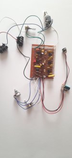
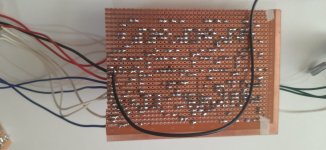
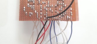
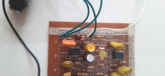
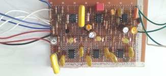
I have built a Mu-tron Phasor 2 Vero board. When the guitar is plugged in and the footswitch is off, I get a clean guitar signal, but when the footswitch is on, I get no guitar signal and hear a tick-tick sound with the LEDs pulsing. The tick-tick response when changing the speed rate value with the pot.
I measured the voltage at the input connection on the board, and it increased when I hit the guitar strings, but the output voltage doesn't change when I hit the guitar.
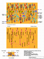
I have also attached the layout that I have followed.
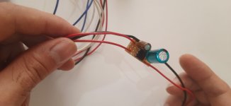
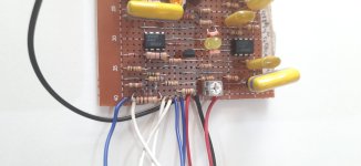
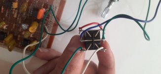
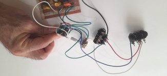
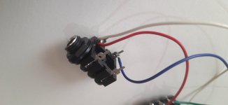
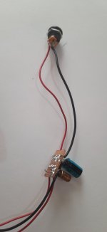
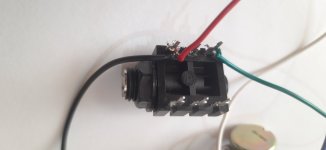
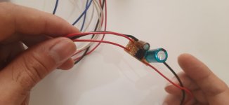
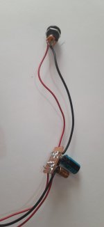
I wired ground from the board to the input jack sleeve, and the input and output points on the board to pins 1 and 4 of footswitch and the input and output jack tips 2 and 5. 3 and 6 are connected to each other.
I have built a Mu-tron Phasor 2 Vero board. When the guitar is plugged in and the footswitch is off, I get a clean guitar signal, but when the footswitch is on, I get no guitar signal and hear a tick-tick sound with the LEDs pulsing. The tick-tick response when changing the speed rate value with the pot.
I measured the voltage at the input connection on the board, and it increased when I hit the guitar strings, but the output voltage doesn't change when I hit the guitar.
I have also attached the layout that I have followed.
I wired ground from the board to the input jack sleeve, and the input and output points on the board to pins 1 and 4 of footswitch and the input and output jack tips 2 and 5. 3 and 6 are connected to each other.
Attachments
-
 20261009_142337.jpg179.1 KB · Views: 10
 -
 20261009_142447 (1).jpg110.1 KB · Views: 8
 -
 20261009_142457.jpg172 KB · Views: 12
 -
 20261009_142534.jpg252 KB · Views: 13
 -
 20261009_142521.jpg144.7 KB · Views: 11
 -
 20261009_142508.jpg174.7 KB · Views: 8
 -
 20261009_142615.jpg146.9 KB · Views: 6
 -
 20261009_142549.jpg171.6 KB · Views: 6
 -
 20261009_142634.jpg117.2 KB · Views: 6
 -
 20261009_142723 (1).jpg117.5 KB · Views: 7
 -
 20261009_142657.jpg241 KB · Views: 7
 -
 20261009_142640.jpg106.8 KB · Views: 7
 -
 20261009_142447.jpg110.1 KB · Views: 5
 -
 20261009_142723.jpg117.5 KB · Views: 9
 -
 Mutron Phasor II.png154.2 KB · Views: 9


 Your advice made me focus on soldering and I saw a bad connection. Thanks.