Need help: first pedal (Aurum) doesn't work

luna

New member
Howdy,

I wanted to learn more about soldering and making electronics, so I bought the Aurum drive and Tommy to learn. I started with the Aurum, but after finishing the soldering process the pedal doesn't work. Since I have no idea where to start looking for the mistakes/errors/issues I'll post here to learn :). I already had contact with the pedalpcb email address, since I suspected I did the jack wiring the wrong way around, so I have switched those around now, but the problem persists.

What does work currently:
- When you press the foot switch, the led will turn on.
- When the led is on (engaged foot switch), no sound is coming out of the pedal.
- When the led is off (non-engaged foot switch), my uncolored guitar signal is coming through.
- Nothing else.

What did work with switched jack wires (as I had previously, yellow on long/outer ring and blue on short/inner ring):
- When you press the footswitch, the led will turn on.
- When the led is on (engaged foot switch), my uncolored guitar signal is coming through.
- When the led is off (non-engaged foot switch), my uncolored guitar signal is coming through.
- The volume control seems to work.
- Nothing else.

Does anyone have any idea what could be wrong/where I can start searching for the problems?

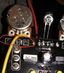
Check the photo below to get an impression of the pedal. I can make more photos if wanted :). Thanks a lot in advance and cheers.


pedalpcb001.jpg
 
Stick a piece of electrical tape or something on the back of your other pots as well. Looks like there could be contact there if a cable was in it.

Try cleaning up your board with a toothbrush and isopropyl alcohol, those stray little bits of solder and wire can inadvertently ground something out.

Not much else I can see visually aside from maybe a few potentially cold solder joints...I’d hold the iron to the solder side of your pot legs for a few seconds and get those globs of solder moving through the holes.

Hi, thanks for the response, I appreciate it.

1. I'll make sure the potmeters are taped up.
2. I found some alcohol (ethanol with isopropyl) and an old toothbrush so will clean it after dinner :).
3. I'm not 100% sure what you mean, but will also try to get the solder through the holes on the potmeters.
 
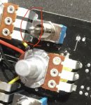
Check your pot lug solder pads, on the component side of the board there is quite a bit of solder...on the solder side there is very little. Just warm it up and get it flowing! :)

3D62DA05-DBEC-4B75-BDF9-1244C09D9F63.jpeg
0C1954B1-D649-4EFC-A499-A88BE18943D4.jpeg
 
Ah! Thanks for the clarification! Going to do that now :). I also cleaned it with alcohol and a toothbrush (and a smaller brush for the small spaces).
 
Done. It wasn't as easy as I would have thought, since the solder didn't want to go through the minuscule hole. So I put some additional solder on the other side so all pot-pcb connections are good on both sides. I also cleaned it again. The first time I was a little bit too careful I think, since there was some rosin residue left here and there. I'm going to let it dry now for a bit and then try it again without the enclosure (then I can check wires for contact and stuff).
 
Unfortunately it didn't work :(. Still no sound from the circuit.

1. Do I have the jack wiring correct? Because at first I had it the other way around.
2. Is it possible that a part is the wrong way around? I didn't look for the right position for the leds, transistors, foot switch and 3-way-switches since I guessed this doesn't matter with these parts. But correct me if I am wrong.
3. Is it possible that a part is simply 'broken'?
4) What can I do to troubleshoot further?
 
1. I’m not familiar w those jacks to know from your description. Whichever lug connects with the sleeve of the 1/4 cable should go to ground. Whichever lug connects to the tip of the cable is your signal which should go to the footswitch board.
2. All your parts look like they’re in right. But I can’t tell about the leds. They must be installed opposite ways to get the clipping right, but that wouldn’t give you the issues you’re having. If you look close inside the led you can see the larger triangle plate is the negative side.
3. Yes
4. I’d for the correct voltages on the pins of the op amp. 8 should be around 9v, 4 should be 0v, and the rest of the pins should be around 4.5v. To test, out multimeter is Vdc mode, touch the black probe to ground somewhere, and the red probe to the pin you want to test. Next, I’d make an audio probe (it’s simple, google for instructions). Referencing the schematic, test points along the signal flow to see where your losing audio. If you get to that point and need more help, just ask!

Thanks for replying!

1. Then they are correct now! The tip sleeves are connected to the foot switch board.
2. I just looked at the LEDs and when you have the IC on the bottom, the left led triangle is on the bottom of the led and the right led triangle is on the top of the led. This is correctly installed? I installed the led triangle sides in the round (instead of square) PCB-holes because of OCD, but now it seems that was the right way to do it :p.
3. Meh :(. That's probably impossible to find out for a beginner like me?
4. Let me check if I have a multimeter. Otherwise I have to buy one I guess.
 
Unfortunately I don't own a multimeter so I will buy one. Do you think it is wise to start on the other pedal kit I have bought in the meanwhile? What if I make the same mistake again and end up with two broken pedals?
 
Yeah having a multimeter is pretty indispensable for the hobby so I don't think you'll regret the purchase.

I said yes that it's possible that one of your components is broken, however, I'd honestly say it's more likely that you have a mistake since it's your first build, than a bad part, because in my experience that's fairly rare (just my take). And with enough patience troubleshooting you could figure out which component (with the audio probe and multimeter).

you could still try the audio probe route in the meantime while you wait to get a meter.
 
I ordered a multimeter (made it a fine one for futureproofness) and it will be here in a couple of days. If I have energy I'll try the audio probe tomorrow.
 
Back
Top