Depattern
Active member
this is probably a lost cause since im not skilled enough to properly troubleshoot. I have a multimeter but aside from basic voltage and continuity testing, i dont really know what im doing but i wanted to give it a shot after buying the pcb and jfets 3 separate times.
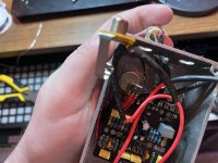
i thought i accounted for the dumb obvious mistakes in my first two builds (soldering the wrong component or pad, then severely botching the desoldering - im really bad at desoldering), and i felt like i did everything according to the instructions i had here. im 95% sure i didnt use any incorrect components like 470k vs 470r, and r2 is 47k. everything is oriented properly. q2 is only soldered like that because i was trying to get ai to help me and it wanted to me swap that jfet for another one due to the weird drain voltages:

but i think the orientation is correct (d,s,g from left to right when facing the top of the pcb). and the pins are soldered on the top and bottom. I know my soldering is shotty but the continuity tests ive done dont show any obvious issues
this is what i have so far:
I don't know if this is enough info for direct troubleshooting but im wondering if anything glaring sticks out, maybe even the poor soldering? although i have reflowed almost every single point that was even slightly dull but there are some bigger blobs remaining which ive attempted to re-do a few times. the jacks and power connections especially are bad due to the twisted awg wire, but those dont seem to be the issue as far as i can tell(?)
i used film caps for the first 2, then i bought a bulk box film cap pack for this one. i had some others on order from stompbox parts but they didnt arrive in time for this one. thats what the yellow 100n (104 100v) and 10n (103 100v) are
maybe someone as unskilled shouldn't be attempting this but i would really love to give this pedal a shot and i feel that it would be so much more satisfying that just buying another pre-built fuzz, even though i may unfortunately end up with no choice. it seems like a really rewarding pedal to build: the kind of overdriven tones, the unruly gnarly timbres, the chaotic biasing.
so really, any general troubleshooting or any ideas at all that maybe you would try yourself if you werent sure why a pedal build isnt working would be very helpful. claude ai usually does not steer me wrong but its been sending me down some mind numbing rabbit holes that arent helping with these builds at all
kind of a sentimental thing, as i had the genius idea of dedicating it to my dog who passed recently. so feels extra depressing to leave it broken
i thought i accounted for the dumb obvious mistakes in my first two builds (soldering the wrong component or pad, then severely botching the desoldering - im really bad at desoldering), and i felt like i did everything according to the instructions i had here. im 95% sure i didnt use any incorrect components like 470k vs 470r, and r2 is 47k. everything is oriented properly. q2 is only soldered like that because i was trying to get ai to help me and it wanted to me swap that jfet for another one due to the weird drain voltages:
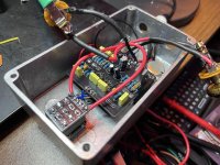
but i think the orientation is correct (d,s,g from left to right when facing the top of the pcb). and the pins are soldered on the top and bottom. I know my soldering is shotty but the continuity tests ive done dont show any obvious issues
this is what i have so far:
- Q1 D: 8.06V
- Q2 D: 8.93V
- Q3 D: 1.248V
- Q4 collector: 3.9V
- Supply: 9.41V
- All carrier orientations verified (potentially)
- All resistors measured correctly (mostly)
I don't know if this is enough info for direct troubleshooting but im wondering if anything glaring sticks out, maybe even the poor soldering? although i have reflowed almost every single point that was even slightly dull but there are some bigger blobs remaining which ive attempted to re-do a few times. the jacks and power connections especially are bad due to the twisted awg wire, but those dont seem to be the issue as far as i can tell(?)
i used film caps for the first 2, then i bought a bulk box film cap pack for this one. i had some others on order from stompbox parts but they didnt arrive in time for this one. thats what the yellow 100n (104 100v) and 10n (103 100v) are
maybe someone as unskilled shouldn't be attempting this but i would really love to give this pedal a shot and i feel that it would be so much more satisfying that just buying another pre-built fuzz, even though i may unfortunately end up with no choice. it seems like a really rewarding pedal to build: the kind of overdriven tones, the unruly gnarly timbres, the chaotic biasing.
so really, any general troubleshooting or any ideas at all that maybe you would try yourself if you werent sure why a pedal build isnt working would be very helpful. claude ai usually does not steer me wrong but its been sending me down some mind numbing rabbit holes that arent helping with these builds at all
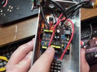
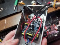
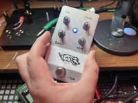
kind of a sentimental thing, as i had the genius idea of dedicating it to my dog who passed recently. so feels extra depressing to leave it broken