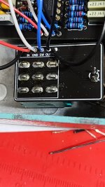
New LED breakout boards

To use the new LED breakout boards, am I correct in assuming that the thinking is to bridge the LED pads on the main pcb so that +9v is present on the SW pad? Otherwise I'm unclear how positive voltage would be available to the LED on the breakout board.

I've always understood it to be a bad idea to apply positive dc voltage directly to a mechanical switch that is also carrying an ac audio signal, even though they aren't on the same poles. Is that concern overblown? I've never tried it.
 
Yeah, I assume you have to bridge the LED.

I've actually done this when using other vendors breakout boards (it's very common to have LEDs/power on the breakout boards, and never had any issues with this).
 
The concern isn’t whether or not there’s positive dc voltage on the board, but if it were directly connected to one of the lugs on the switch. But after thinking about it more, it seems like the sw pad is probably routed through the LED circuit before connecting to the switch.

So basically, never mind. Carry on.
 
  • Like
Reactions: spi
So if you're using one of these, would you have to jumper the LED resistor on the main board? For instance, a 4.7k resistor on the main board now gets jumpered and the 4.7k resistor moves to the breakout board?

Also, how do we figure out how far away the LED hole is from the footswitch hole?
 
Yeah, seems like you would jumper the led pad and the resistor, or you could leave them empty and wire the SW pad on the breakout board directly to 9v. And you would use a 4.7k on the version without the brightness control, but a smaller value (maybe 1k?) with the brightness control.

Your other question is a good one, a drill template would be handy. But no real harm in guessing as close as you can and having it at a slight angle.
 
That's a fair point about being a little off. Any idea of what value trim pot to use here? Would have been nice to have a quick BOM and drill template at least, but I'm a noob lol
 
To use the new LED breakout boards, am I correct in assuming that the thinking is to bridge the LED pads on the main pcb so that +9v is present on the SW pad? Otherwise I'm unclear how positive voltage would be available to the LED on the breakout board.

I've always understood it to be a bad idea to apply positive dc voltage directly to a mechanical switch that is also carrying an ac audio signal, even though they aren't on the same poles. Is that concern overblown? I've never tried it.
Hi Jesse,
Would you still have this available to take a photo to see what solution you used?
I purchased a

3PDT Breakout Board with LED​

and the LED doesn't light up.

Thank you.

 
Back
Top Bottom