No sound on first stripboard fuzz attempt

SeaDub71

New member
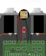
I've been trying to build (what I thought was) a simple Ritual fuzz on this stripboard. I'm using the schematic in the included photo.

All I can say is that I've looked closely at every hole, and everything appears to be firmly in place. I've checked the positions, and I've used my magnifying goggles to inspect the channels, ensuring that nothing is crossing over and that the holes completely sever the copper. But I'm getting no guitar sound, just some light humming.

Two other important notes: First, I didn't have a 680p capacitor, but Gemini tells me a 1uf electrolytic cap would be an OK substitute and that the negative end would go up closer to the red wire. I realize AI is not actually intelligent, so maybe that was a mistake? I also searched for the pinout on these 2N2222A transistors and I believe they're in the right direction with the flat side facing the right (they're in some pinouts here). Otherwise, the values all match the schematic.

I also had to combine a couple resistors to get the right values and have done that before, so I don't think that's the issue here.

Is there anything obvious I've done wrong here? I've done a couple PCB builds that eventually worked but this is my first attempt at a stripboard build.
IMG_8846.jpeg
IMG_8849.jpeg IMG_8843.png
 
I think your 9V jack red (+) and black (-) are swapped. That is, assuming you're using center-negative 9V plug like all pedals. There's no protection diode so it's possible that the reverse voltage hook-up damaged the transistors or electrolytic caps. (I'm guessing not, but it's possible that you reverse those wires and it still doesn't work.

Also, your output jack (connected to Vol pin1) ground is is not connected to the board ground. Add a wire from Vol pin1 OR the output jack ground to either the board gnd or the input jack ground.

After those are fixed, if it still doesn't work, then next I'd say to make a simple Audio Probe (just a jack and a capacitor and some wires), to trace how far the audio gets in the circuit.

By the way, for that type of pot, I would recommend using the skinny pins and bending them into a U shape, then bending your wire into a U shape and hooking them together, squeezing them tight with pliers, and solder. Using the holes where you did will be more likelihood of over-heating the resistive trace (in my opinion). Best case would be to get pots with solder lugs (circles) to hook the wire into. Not sure you need to re-do these, but just a tip.

Otherwise, the pics are not really clear enough to analyze.
Thanks, the 9V thing may be it. When I search for how to wire that part, I see examples saying the flat, 90-degree part is the negative and examples saying it's the positive, and I always forget what I did in my other pedals. I need to just take a photo of it. Either way, I tried the reverse configuration first and still got no sound. But like you said, maybe I have now burned out the transistors and caps doing it backwards.

On the output jack ground, does that have to connect to the board's ground? Or just any ground? When I rigged it up to test it, I did connect it to one of the jacks' ground and that killed an obvious loud hum, so I assumed that was fine.
 
I think your 9V jack red (+) and black (-) are swapped. That is, assuming you're using center-negative 9V plug like all pedals.
+1

this is how the jack needs to be hooked up:
1770953852707.png

also - from the photos, it doesn't appear that all of your ground wires have continuity with each other. they should.
- great way to do this is to ensure that all ground wires meet at the input jack sleeve.
 
Back
Top