Nobelium Build 50kHz issue

Quoshy

New member
Hi all,

been a huge fan of the Noble DI but never wanted to spend 2k and wait a year for the real deal to be shipped to Europe, so when I saw the Nobelium I immeadiately had to order the PCB and build it.

Was successful and I truly believe this thing has great potential but I noticed an issue which I wonder if it is a problem with the (power supply) design or just an issue I have.

There is a huge 50kHz issue with my build in the audio path (its not audible since its far greater than 20kHz) but I think it steals internal audio headroom making it sound worse than it could. It depends on the low voltage supply and is substantially worst at 12V supply compared to 9V.

Attached is my oscilloscope screenshot measuring the output jack voltage with no bass plugged into the input. Does anyone else see this 50kHz wave with their builds and is this hence a general issue presumably caused by the power supply design here?

Thanks.
 

Attachments

  • 20240831_183242.jpg
    20240831_183242.jpg
    290.9 KB · Views: 15
It is the "feature" of the onboard PSU. A switched mode boost converter runs most probably on that 50kHz frequency. The problem is it is located very close to all the analog traces so it gets inducted on them. You might try redesigning it by finding optimal component values to have more efficient PSU with lower ripple but it will never be perfect. It is the price of having a physically small PSU in comparison to using a transformer for example.
 
Thanks. I noticed 2 problems with the sound I get with the Nobelium:
1.Missing dynamic range, specifically a light touch will not produce enough power, almost feels noise gated.
2. Low B-string too muddy

I could imagine this power supply issue is the reason for it cause that 50kHz noise has such a high level when amplified although its not audible, but just kills the audio headroom and buries the "payload" audio. Thatd be a pity, because the Nobelium has some weight and depth to the sound, especially the A- and D-strings of my basses sound awesome through it. And I do own a lot of high end bass preamps /DIs. The Nobelium would beat them if it wasnt for the 2 issues I notice in the sound. Maybe thats exactly the difference to the real Noble DI any professional will not accept soundwise.
 
Thanks. I noticed 2 problems with the sound I get with the Nobelium:
1.Missing dynamic range, specifically a light touch will not produce enough power, almost feels noise gated.
2. Low B-string too muddy
That sounds like there's something wrong with the pedal. Can I ask what power supply you're using with your Nobelium?
 
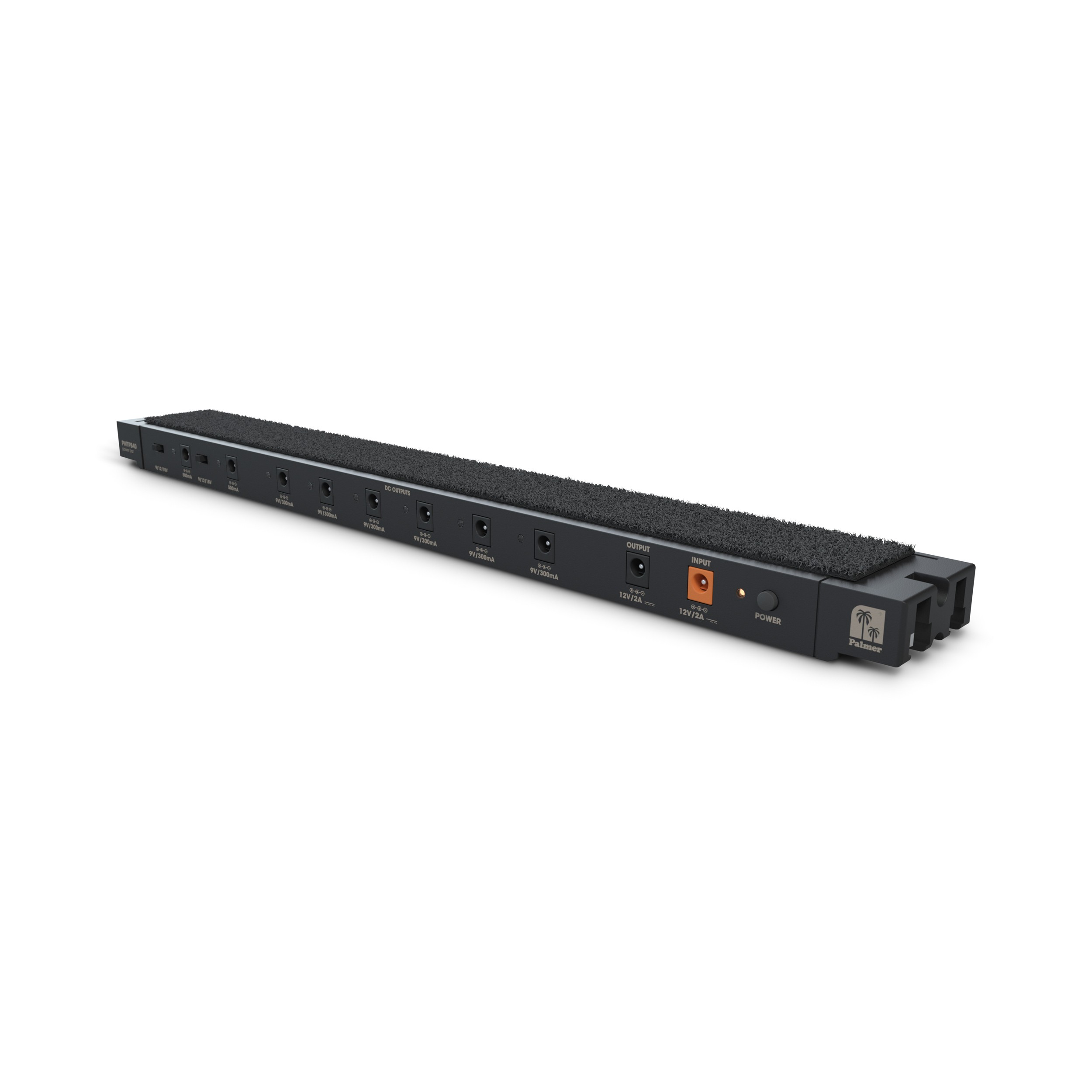
I'm using the power supply built into my Palmer pedalbay40 pedalboard. It was cheap and I dont think its good thats why Ive been thinking about getting a good pedal supply. But is the Nobelium internal PSU running at 50kHz or is it my Palmer?

Again its worst when I supply it with 12V DC from the Palmer. A digital multimeter shows a reading of >100mV rms on the output jack without any input plugged in. I noticed it cause my mixing board showed -15db input level with no volume coming from my bass which is a huge level and since its quiet I suspected either DC offset or >20kHz frequencies in my Nobeliums audio path. So I took a digital multimeter first and then the oscilloscope screenshot to find the 50khz culprit. With 9V supply my digital multimeter reads "only" 10mV on the output jack. I havent taken the oscilloscope but I'd expect the 50khz wave just to be 10x smaller here. I feel if I could get rid of the non audible noise in the audio path the Nobelium would unleash its full potential and become my main bass preamp a thats really a statement considering I'm used to some of the best pre's /DIs a bass player can own
 
Are you using the Palmer PWT-08 power supply ?

The best way to check the power supply noise issue is to hook the pedal up to a battery and run the test again, a car / motorcycle / ride on mower etc battery should be fine to supply a clean 12v supply.
If you can build a pedal you can work out how to do that.
Remember that the tube heaters are running direct of the supply so stay below 14.16V going into the pedal.
(Tubes can run at 12.6V +10% = 13.86V, and a drop of 0.3V across the 1N5817 diode = 14.16V max supply to the pedal)
 
Last edited:
I'm using the power supply built into my Palmer pedalbay40 pedalboard. It was cheap and I dont think its good thats why Ive been thinking about getting a good pedal supply. But is the Nobelium internal PSU running at 50kHz or is it my Palmer?
I'm not as concerned with the output ripple/noise of the power supply as I am with the output current rating. 99% of the time people have issues with tube pedals it is because they are not providing enough current to the pedal.

I also want to clarify that
There is a huge 50kHz issue with my build in the audio path (its not audible since its far greater than 20kHz) but I think it steals internal audio headroom making it sound worse than it could.
This is not how audio amplification works. Power supply ripple outside of the audio frequency range cannot "steal headroom" from the amplifier.

It sounds to me like something is wrong with your build. Please post pictures of the build and details of your power supply so we can help figure out what's going on.

There are literally hundreds of Nobelium units out in the world and they absolutely are being used in professional touring and recording environments.
 
Palmer has 2A output. Thats plenty to supply the Nobelium.
This is not how audio amplification works. Power supply ripple outside of the audio frequency range cannot "steal headroom" from the amplifier.
Yes it can. Imagine you have 1V headroom. You add 0.5V DC offset. What audio amplitude (of any frequncies) can you add before it starts clipping? Exactly - another 0.5V. Actually if youve ever built a distortion pedal and understood the schematic, this happens all the time (but on purpose). Same goes for other frequencies which you dont want in your audio like it happens here. Actually good mixing engineers do this all the time: high and low pass filtering any instrument to the frequency content the instrument shines at and cutting anything that would just "steal" headroom. My build should be fine. It's either my Palmer PSU or the internal PSU thats the issue. I'll hook up a battery and find out the next couple of days and let you know.
There are literally hundreds of Nobelium units out in the world and they absolutely are being used in professional touring and recording environments.
Yup, I would too if it wasnt for the 2 issues I noticed when comparing to my other high end pres (Caveman (Neve1073), Aguilar, Rheingold, Radial,...). I'm pretty sure the audio path itself is the real deal - like I said: my basses A- and D-strings absolutely killer through it. E- and G-strings fine. Anything on the low B unfortunately no match to the other stuff I have. Pretty sure the real deal wouldnt have these issues, and very likely to me the power supply is the culprit.
 
I don't know shit but I haven't experienced this with my 5 string. I also blast my Nobelium with an 0c2, HOG, meatbox and arcadiator constantly with glorious results. You got a buddy with a 1A one spot laying around?
 
Last edited:
Don't get me wrong: my Nobelium doesnt sound "bad", probably a lot of decent bass players wouldn't even notice the 2 sound "issues" I mentioned. They are anything but obvious. Its just that I'm super nerdy about it and something that's only 95% there soundwise will not make me happy anymore considering I've been spoiled with all the good stuff I'm having access too. I'll test the next couple of days. Just need to find time
 
I'll test the next couple of days. Just need to find time
And please post some pictures, they are very much appreciated around here whether there are problems or not.
Include a pedal board shot with some of your other pedals if you can. :)
Thanks
Michael

EDIT: It looks like that pedalboard comes with a WT PB 40 power board, it has 2 outputs at 9/12/18V at 500mA and 6 outputs at 9V 300mA and also an output that says 12V 2A that can feed another power board. (Most likely the 12V 2A outlet is not filtered and it is not isolated like the others)

The power supply has a wall wart that feeds the pedalboard power supply, and it says in the manual the total max amps is 2A, that would be all the outputs combined..

So you can run at 12V 500mA max or 9V 500mA max on the the variable voltage outlets, you would be better of using the 9V setting as the Nobelium uses less power at 9V.
The high voltage stays the same in the Nobelium but the tube heaters are fed from the input voltage, the tube heaters use less amps at 9V compared to 12V. (They take a bit longer to heat up at 9V )

 
Last edited:
Did a quick and dirty setup, cutting a pedal supply cable in half and hooking up my lab dc supply: my build takes typ. 440mA at 9V and 470mA at 12V. The lab supply is clearly better than my Palmer (audible noise frequencies /hiss is reduced). I think I need to treat my pedals to a decent supply in general. Never really thought much about spending a lot on a pedal supply.

However I still get a signal lamp reading on my mixing desk after amplifying by +30 to 40db even though its not audible. If I had a couple of 9V batteries with clips, I would wire them in parallel to get the cleanest possible 9V DC, but I'll save myself the effort since I need to get a decent pedal supply anyway now that Ive made up my mind.

I still consider it most likely that there might be a general issue with the internal PSU by design. It's just extremely likely with that packaging without internal shielding that this switched mode circuit emits a great deal of EMI that gets injected in the audio path. Perhaps the guy who builds the real deal Noble has this all figured out. He'd not be very intelligent if he used all these huge components to create a stable HV DC from mains AC for no reason. If you could just get away with an internal PSU design like the one in the Nobelium to create a stable DC without those high non audible dirt frequencies radiating, anyone who wouldnt make use of this would just not be very smart.
 

Attachments

  • 20240902_192213.jpg
    20240902_192213.jpg
    485.2 KB · Views: 28
  • 20240902_192128.jpg
    20240902_192128.jpg
    450.5 KB · Views: 27
  • 20240902_192256.jpg
    20240902_192256.jpg
    277.4 KB · Views: 27
The 50kHz makes sense because of the 555 timer operating in astable mode. It's essentially putting out a square wave that drives the gate of the mosfet at M1.

If you look at the power supply schematic, the frequency is determined by R3, R5, and C4 which come out to be about 46kHz. But there is also a feedback loop at R1 through Q1 that connects to pin 5 of the 555 timer. This is used to keep a constant 250V under load by varying the square wave that drives the gate. It's a simple DC boost circuit.
 
Did some testing again. The SMPS creates the ~50kHz, not the 9-12V DC supplies I've used.

Can anyone with an osciloscope do me a favor and measure the voltage at the 1/4" output jack on their build with volume fully cranked and bass/treble all the way off? And then also the XLR out Pin1 vs GND (i.e. housing)?
I get the worst ~50kHz on the XLR Pin1, which actually is the ground pin of the 3 and should ideally be 0V vs housing but theres a peak of around 200mV on it with my build...

Also fun experiment: with an open housing lid it becomes even worse (not much but clearly visible). If I slide the lid then slowly from the tubes towards the SMPS mosfet it improves until the mosfet is fully covered, showing some effective shielding.

Can anyone confirm?

I just did some quick research on this circuit (found it to be the "nixie" SMPS). Although I have a university degree in electrical engineering I consider myself a non-expert in this field of circuits, but I've seen people who know better point out how this SMPS design is flawed basically all over the place. But Ive not seen anyone comment on EMI aspects here and how this might really inject massive dirt into the audio path if used in audio equipment. It's not "directly audible" (since >20kHz), but there's something that makes me think it does compromise headroom and hence audio quality in whatever amplifier its sent to if there's no low pass filter that rolls all the HF dirt off.
I'm measuring 880mV peak to peak at the output jack and 76mV peak to peak between XLR pin 3 and the output jack ground.

I also have a university degree in electrical engineering and I spent my first few years in industry designing SMPS circuits. I can tell you that the nixie supply used here (and in many other tube pedal designs) is far from ideal because NE555 was never designed to be an SMPS controller. It is inefficient, and there is no proper feedback system to allow actual what we consider actual regulation. So why do I and countless others use it in pedals? Because it is inexpensive and uses easily sourced components.

Jack, the designer of the Noble preamp, does not use an SMPS, he uses a power transformer and a rectifier, like typical tube amps. The power transformer he uses is custom made for him, and is the most expensive component of the whole unit. This preamp could easily be made with a comparable off-the-shelf transformer, and it should not be difficult to find one that is suitable. From there you could determine how much noise you consider "acceptable" and design appropriate filtering for it.

Alternatively, as a cost-saving measure, you could add additional filtering to an SMPS to save space in your build and still reduce the output ripple from the SMPS. We already know what frequency to target, it would be trivial to design a suitable LPF that would handle a low-current supply like this one, it's just a matter of how much output ripple is acceptable.
 
Something seems to be wrong with either my USB drive or the oscilloscope's image capture, but here are some lovely garbled pics of the measurements. You can still see the important bits I guess.

Output jack tip measured with reference to output jack sleeve:

pic_33_3.jpg

XLR pin 3 measured with reference to output jack sleeve:

pic_33_4.jpg
 
Thanks for quick reply and very interesting comments. Your readings are slightly higher than the ones I got yesterday but they confirm the finding and are clone tobte ones I got 3months ago.

XLR pins 2 and 3 (+ & -) below 100mV w/ reference to GND. I get the worst on XLR pin 1 (i.e. the GND XLR pin) with reference to housing (GND) even when I hook up an additional wire between them. It's crazy. You'd think with or without a wire between them there should be 0V as they are electrically connected either way. But you get the highest voltage right there on the XLR GND pin. If connected to a mixing desk this huge EMI remains the same on the XLR GND pin and this is how I came to know about this and started this thread because I saw this huge level after setting the desk input gain to 30-40db. It's dead quiet but so much going in the 50+ kHz region. There's also where I noted the missing headroom / dynamics effect cause the bass payload audio does not have much space till it hits 0db on the mixing desk.

I'm very surprised Jack would spend so much on the power tranny. The XLR Jensen is already almost 100bucks. Why would you spend even more on just the power supply? Only makes sense to me if he found out you can't make it work with an SMPS for exactly the reason we are discussing in this thread.

But I'd still be interested in what you could achieve with a best practice lowest EMI SMPS here. One that uses a modern chip and also quiet a few additional filtering caps and inductor on the LV side of the converter (passive EMI filtering network). Should still be 10x more cost & space effective than a power tranny / AC mains to DC.
 
Back
Top