Noisy PCB, breadboard version silent

acuevo

Member
Hello everyone. Here i am with my first distortion PCB, which works, but has a lot of hum when gain is turned up past 8. Becomes much worse when tone and presence are turned up.

Tone is pregain, presence is post gain.

Weird thing is when i breadboard this its no more noisy than any other high gain pedal - and thats even with it getting power from a different outlet than the rest of my pedalboard.

About the noise - low hum, not like a single coil, just what you’d expect from high gain but much louder. Goes away when turning the guitar down, goes away when playing a buffered guitar. Buffered pedal in front makes no difference.

I am convinced its not an issue with the guitar, as other high gain pedals and also the breadboard do not cause this issue with the same guitar.

I believe something in my layout is not agreeing and for the life of me i can’t figure out what. I’m very new so i know there are lots of mistakes, and i’ve even learned more since i had the boards made. But i wanted some feedback before i waste more money on a bunch of “this MIGHT fix its”.

I want to learn how to do this properly, and repeatably.

I will post pics in next post. Be kind 😅 i know there are some questionable choices on the board, i just don’t know enough to know how to fix them yet lol.
 
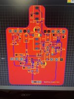
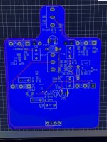
IMG_2624.jpeg IMG_2625.jpeg

My thoughts -

op amp input traces could be shorter?

9v for U1 running too close under input section?

too long a trace between R5 and C5? possibly getting interference from the LED trace or the gain pot?

need ground vias for some sections that maybe don’t have the best paths to ground?
 
You may have a few issues at play, but it's most likely cross talk between the power section and audio section. From what I've heard with PCB design is to keep the traces short and both sections mentioned previously far apart. You also have a lot of empty space in your PCB, so perhaps a redesign is in order. Do you have a pic of your completed build? There are ways around that too. For example, keeping your input and output wires as far apart as possible from each other and not having them overlap the PCB. You could also get away with installing shielded wire for the Input/Output (you'll need to connect the shield of each one to ground).

Just my 2 cents, but I'm sure the PCB designers here could offer some better tips.
 
I won't say I'm great at PCB design, but I try to keep all power related things in one area of the PCB and then try not to have voltage and signal traces get too close to one another. I'd probably re layout your board trying to keep the power section away from the rest of your signal section.
 
i am not sure why i left all that open space at the bottom 😂 just now noticing.

among the things i’m going to try with the redesign is flipping U1 around so the 9v can go in the top rather than the other side. then just swap the roles of U1.1 and 1.2.
 
With an audio probe, can you see where the hum starts? It might be helpful to find where the hum starts so you know where to focus your efforts.

I think you could keep more of the backside routing on the top to keep a more continuous ground plane on the back (e.g. it looks like vref could be entirely top side, you could move R5->C5 to the outside of pad 3 of GAIN to keep the GAIN3->DEEP2 on the top side, etc)

Also you could go SMD on the diodes if you wanted to (e.g. 1N5819WS/C191023 for polarity protection, 1N4148WS/C2128 for clipping, both Basic parts).

I've had boards where I've just had a hell of a time getting it quiet as well. I went through a bunch of revisions of the Tommy/Timmy before I got something that was quiet. The last main revision, I ended up putting in a DIP-8 socket for the op-amp and that ended up fixing it, maybe the small clearances on the SOIC-8's were allowing some feedback. But I also made some other changes at the same time, shotgun style, because it's too expensive to get stuff fabbed to test just one change at a time -- I changed out the capacitor values to the original 820nF instead of the 1uFs I had on hand, and added some additional capacitance close to the feedback pins, and made sure that there was a large amount of clearance between traces that ran parallel.

Also while iterating on this same board, I was able to get the previous revision quieter by being very careful about my input and output wires. They're long antennas. It looks like in the current form of your build they might pass right over the gain stages. You might try taking your current build and get the input and output wires as far away from the board as possible and test it out. This might be why it worked better on the breadboard, because your input/output wires were far away from the gain stages. If this works, you could try using shielded wires, or just be really careful about the interior wire routing.
Good call on audio probe! I will hack one together later this week and test for that!

You are correct that the input wire runs straight over the board and down to the 3pdt. I’ve been comparing to an Abasi Pathos (highest gain pedal i have) and even out of its enclosure it makes less noise when cranked BUT it has no input wire… board mounted jacks. So just guessing but there must be enough ground around the input trace to shield it on that board. I’ll have to see if i’ve got any shielded wire laying around lol

I hesitated to run the R5-C5 trace on the outside of the gain 3 pad due to the 9v LED trace running on the bottom side right there. But yes i considered that as well, because i really did want to have gain 3-deep 2 on the top side. I will give that a try though if you think running over that 9v trace is ok. I’m here to learn 😁

I routed vref on the bottom only because routing it on top interrupted the ground plane right there. In hind sight it was silly as i could have just slapped a ground via in that spot.

Thank you sir once again for your input, it’s proving to be very helpful to me!
 
I’ll have to see if i’ve got any shielded wire laying around lol

Have you tried it out of the enclosure, like just moving the input wire out of the way? (Rather than going thru the hassle of shielded wire). I think that'll help figure out whether or not shielded wire would help.

I think running near/over the 9v rail is probably ok, though maybe not paralleling it the whole way. I'm usually not too careful about it. I also have decoupling caps on all of the op-amps which I think will help with noise. (It looks like you have one on U1 but not U2 - you might add a decoupling cap there too)

Oh and actually, speaking of ground vias, I might add a ground via at every SMD ground - your rear copper is much more intact so try to get stuff to ground there. Some of the SMD grounds on the top have kind of a circuitous route.
 
Back
Top