Parentheses not working.

turntablemonkey

New member
Hey I have recently built the parentheses fuzz but can't seem to get it to work. The boost, octave and distortion leds light up but not the other one, I believe it may be the clipping one? Dry signal passes through and with the boost switch engaged it boosts the signal slightly but I'm not sure if it should be louder, it's a very mild boost.
Engaging the distortion switch kills the signal. I've been over the board and am fairly confident that there are no shorts. I'm pretty new to building pedals and electronics in general so I'm not sure where to begin testing or if anything looks wrong. Any help would be very much appreciated. pg44rLN.jpeg
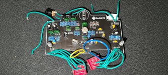
 
Are those ceramic or tantalum caps in place of the electrolytics? And maybe an electrolytic where a film cap is labeled?

Edit: Not sure C22 will work with an electrolytic. Someone else will know for sure.

It's usually a good idea to stick with the cap type suggested on the screen print while learning.
 
Last edited:
Sure is :( it was the first one I built and I've learnt a little more since then. Didn't occur to me until you mentioned it that it could be an issue. Could I have blown any components by doing this? I've ordered the correct caps now.
 
Ok, I've swapped out the capacitors for the correct types. Still the exact same issue. The boost side seems to work well but as soon as I turn on the distortion switch it kills the signal. Also the internal clipping led doesn't light up. Could the problem be that I've added the two optional diodes without adding a switch for it? I'm at a complete loss as of what to do or check now.
 
Last edited:
Check these voltages with respect to ground. Power on, pedal in bypass.

Q1-S (middle pin).
Q5-S.
Q6-D (left pin).
IC1-6.
Voltage on each side of R18.

We'll see where that leads us.

The DIST, OCTAVE & BOOST LEDs are usually mounted on the solder side of the board. The clipping LED (D4) is usually mounted on the component side of the board. It will light up a little when the distortion part of the circuit is working.

Q1 - 0.730V

Q2 - 0.818V

Q6 - 4.676V

IC1 - 4.178V

R18 - 4.591V

Thanks, really appreciate this help. Planning on swapping the indicator leds to the other side if I can get this thing working.
 
Q1 - 0.730V - OK

Q2 - 0.818V - I asked for Q5

Q6 - 4.676V - OK

IC1 - 4.178V - OK

R18 - 4.591V - OK

Thanks, really appreciate this help. Planning on swapping the indicator leds to the other side if I can get this thing working.

Q1 is at the low end of the spec, but it's ok for how EQD designed this pedal.

The maximum BOOST gain depends on what is driving the pedal. With a low-impedance source, you should be able to get over 20dB.
 
In that case, all of the DC measurements are good. Check for bad solder joints, incorrect component values. We can't read any of your capacitors. Stranded wire is notorious for fraying at the solder joints and shorting to the next pad, so check for that.
 
I just gave it a quick look over and somthing weird that I noticed is that I need to solder in the overdrive led backwards for it to light up when the switch is pressed. It doesn't light up at all with the cathode soldered to the "k pad", could this indicate anything? Looks like I'll be needing to make an audio probe. Thanks again for your help.
 
Back
Top