Parenthesis Fuzz No Power

andihow

New member
Hi All,
I'm a total noob to this pedalbuilding thing. I'm thinking perhaps I should have chosen a more simple circuit as my first build but here I am.
I'm pretty sure I did everything correctly in terms of what goes where, maybe a few of my connections are cold, but I'm not sure how to figure out if that's the case.

When I plug in the pedal the bypass works, but engaging any of the 3 footswitches just makes it go silent. Also no love from the LED's. My first guess is that i should plug in the unit and use the multimeter beep setting and keep the red multimeter pin on the + from the power adapter and just move the black down the signal chain according to the schematic. Would this be a proper way to troubleshoot this? Also, here's a pic of what i've done so far, maybe you guys can spot something obvious that I missed. Appreciate the help
IMG_20200315_123450.jpg
 
Hi All,
I'm a total noob to this pedalbuilding thing. I'm thinking perhaps I should have chosen a more simple circuit as my first build but here I am.
I'm pretty sure I did everything correctly in terms of what goes where, maybe a few of my connections are cold, but I'm not sure how to figure out if that's the case.

When I plug in the pedal the bypass works, but engaging any of the 3 footswitches just makes it go silent. Also no love from the LED's. My first guess is that i should plug in the unit and use the multimeter beep setting and keep the red multimeter pin on the + from the power adapter and just move the black down the signal chain according to the schematic. Would this be a proper way to troubleshoot this? Also, here's a pic of what i've done so far, maybe you guys can spot something obvious that I missed. Appreciate the help
View attachment 3463
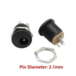
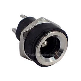
What kind of power jack is that??
Are you sure you have the polarity the right way around???
Oh and you’re missing the led in the clipping section...
 
Hi All,
I'm a total noob to this pedal building thing. I'm thinking perhaps I should have chosen a more simple circuit as my first build but here I am.

Absolutely. Baby steps. You picked one of the hardest pedals to build.

If you want us to inspect that board, take higher-res pics of just the board, both sides.

After you respond K Pedals' comments, power it up and measure the voltage from D100 cathode to ground.
 
The 2 diodes on the left side are upside down D1 and D2
Would this prevent it from working?

What kind of power jack is that??
Are you sure you have the polarity the right way around???
Oh and you’re missing the led in the clipping section...
I got it from tayda, its this kind: https://www.taydaelectronics.com/1614-19-lumberg-dc-power-socket.html

I'm not sure why it has 3 legs, 2 of them seemed to be signal and only one ground, so i clipped off the extra signal one and soldered accordingly. I did indeed have the polarity reversed though. I flipped it and soldered the LED's in, and now thats done when I plug it in and flip a switch the LED's come on. Other than that same behavior as before, when the footswitches are engaged I lose the bypass and get silence, even with the LED's coming on and off as I hit them.

After you respond K Pedals' comments, power it up and measure the voltage from D100 cathode to ground.
I get 9V from GND to D100

Here are some more pics of the board (took the pics before i reversed the polarity and soldered the LED's in.)
closeback.jpg closefront.jpg
 
Would this prevent it from working?


I got it from tayda, its this kind: https://www.taydaelectronics.com/1614-19-lumberg-dc-power-socket.html

I'm not sure why it has 3 legs, 2 of them seemed to be signal and only one ground, so i clipped off the extra signal one and soldered accordingly. I did indeed have the polarity reversed though. I flipped it and soldered the LED's in, and now thats done when I plug it in and flip a switch the LED's come on. Other than that same behavior as before, when the footswitches are engaged I lose the bypass and get silence, even with the LED's coming on and off as I hit them.


I get 9V from GND to D100

Here are some more pics of the board (took the pics before i reversed the polarity and soldered the LED's in.)
View attachment 3466View attachment 3467
I think that jack is gonna cause you problems if you’re using a metal enclosure...
I think you’re gonna wanna use one of these for future reference...

 
No the upside diodes wouldn't keep it from working, but while you got the Iron hot you got some very questionable solder joints, they should look like a tiny shiny Hershey's kiss, anything that doesn't should be reflowed
 
Usually there’s 3 as one is a switched tab for using a battery.

Did you buy this as a kit? If not, where did you source your JFETs?
Didn't buy as a kit, all the parts i got came from either mouser or tayda

I think that jack is gonna cause you problems if you’re using a metal enclosure...
I think you’re gonna wanna use one of these for future reference...

Thank you, will use these for next time

No the upside diodes wouldn't keep it from working, but while you got the Iron hot you got some very questionable solder joints, they should look like a tiny shiny Hershey's kiss, anything that doesn't should be reflowed
Cheers, I'll go back in with the iron tomorrow and try to fix any cold joints.
 
Back
Top