Mikeydubsj
New member
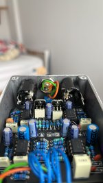
Hey guys, I am building a few Median Compressors, and I just finished my first one and had a few questions as I can't get it to work.
I've been building pedals for a few years, and have learned a lot, but this is my first compressor. There's a few things in this build that I haven't encountered yet. So I apologize if this i'm just missing something stupid, but here is what I've got.
*Main Issue
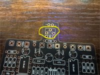
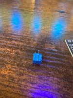
TR1 10K Trimmer potentiometer, 3362P type. The PCB itself has a 5 hole spot for this pot, however the only 3362 types of pots i've seen only have 3 poles. Am I wrong in using this? Is there a different pot that I should be using? If anyone has questions that would be amazing.
IC replacements
I've seen other people using the TL072CP chips as opposed to the OP1678. (I had originally bought the OP1678 and the through hole adapter, but the ICs I bought weren't the right size. I will update that in the future. But will this still work with the TL072CP?
Q1 & Q2
When installing, I used a socket for the transistors for easy access to reversing them in case I got it wrong. Is this a bad practice? I just figured it would make things easier in case I made a mistake.
I've been reading up on how to bias the transistors, but i'm not sure i'm even to that point yet since I can't get any audio out of this circuit. Even if I roll the TR1 from one extreme to the other, I get no signal.
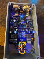
Other than that, I linked a picture of my build in here as well. Any help would be greatly appreciated!
I've been building pedals for a few years, and have learned a lot, but this is my first compressor. There's a few things in this build that I haven't encountered yet. So I apologize if this i'm just missing something stupid, but here is what I've got.
*Main Issue
TR1 10K Trimmer potentiometer, 3362P type. The PCB itself has a 5 hole spot for this pot, however the only 3362 types of pots i've seen only have 3 poles. Am I wrong in using this? Is there a different pot that I should be using? If anyone has questions that would be amazing.
IC replacements
I've seen other people using the TL072CP chips as opposed to the OP1678. (I had originally bought the OP1678 and the through hole adapter, but the ICs I bought weren't the right size. I will update that in the future. But will this still work with the TL072CP?
Q1 & Q2
When installing, I used a socket for the transistors for easy access to reversing them in case I got it wrong. Is this a bad practice? I just figured it would make things easier in case I made a mistake.
I've been reading up on how to bias the transistors, but i'm not sure i'm even to that point yet since I can't get any audio out of this circuit. Even if I roll the TR1 from one extreme to the other, I get no signal.
Other than that, I linked a picture of my build in here as well. Any help would be greatly appreciated!
 ) but everything has connectivity.