Pitch Witch LEDs not working

tranquilthumbs

New member
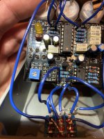
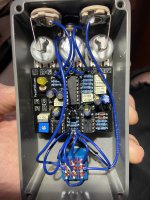
I saw one other post on here talking about both the indicator and LFO LEDs not working but it didn't seem to be resolved. I just finished my build last night and I am having the same issue. The bottom row of pots: Delay, Feedback and Blend are all working fine. The top row is not doing anything since the internal LED wont turn on. I ended up shining a flashlight on the LDR and it works great. When the flashlight is on, the Depth, Speed and Wave do seem to work. So this leads me to believe my only issue is figuring out how to get the LEDs to work. I checked several times and i'm positive the + and - orientation is correct. I also read some places about LED not being grounded or something like that but i'm not sure how to wire things different if thats whats needed. This is only my second pedal so I'm still learning but if anyone could help then it would be so appreciated! Thanks!
IMG_6811.JPG
 
Test the matching colours for Continuity.
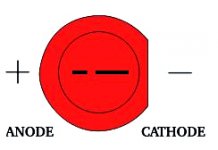
LED1 should have a Flat side on the Left in purple indicating -
Does your On /Off Led work as expected :
I checked all the points you mentioned and they all have continuity. I've also double checked that the anode and cathode of the LED are correctly oriented. My on/off LED does not work either. Everything seems to be working except for the power to my LEDs. I also checked the continuity with my on/off LED to R14 and that seemed good as well. I then checked the 4558 IC to make sure it was getting power and it also seemed good when i touched the + and - of the board.
 
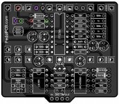
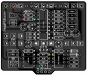
1. Check for Continuity on these matching Colours.
The lower 10K Resistor could be Blue Left & Red on the Right.

2. What is the DC Voltage individually on the Green Rings to Ground, They should all be the same :
Pitchwitch Continuity LED Test.jpg
 
I had to run and get a new multimeter today since i didn't trust the old analog one i was using. There is continuity between all those points but i was having trouble reading the DC voltage because the numbers were jumping around and wouldn't stay put. They each were jumping around the same numbers though. After poking and prodding a while, I plugged it back in and the LFO led is now working but it is really dim so the effect isn't very intense. However, my on/off led is still not working so I'm still trying to figure out why that is not getting power, how to make the internal led brighter, and what went wrong in the first place in case it happens again.
 
Also, Can you LIST resistor colours on R1, R3, R9 & R13 or show clear Picture at that angle?
Did you use a spacer/non conductive pad between the Dual pot & PCB?
 
Thank you both! I definitely have C2 and C3 swapped. I’ll get those set straight right after work today. I’ll also try to get a better reading of the DC voltages on each green circle.
And I have electrical tape on the back of the dual pot. I had only a single piece between the pot and the board and I was starting to wonder if one of the solder points poked through it just enough to ground it out. This is going to be on my mind all day now until I can get off work and gives these fixes a try!
 
This is basically how the Alpha pot is sitting behind the PCB!
A piece of Electrical tape is not Good!
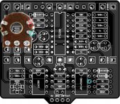
See where the Folded tabs are located - 10k Resistors & 47 uF Electro Cap:

Pitch Witch Gang Pot .jpg

A test to confirm would be to set DMM to Continuity & test between:
1. The Dual Gang Potentiometer metal casing & the Left R14 & R15 -10k Resistor pads from the component side.
2. Dual Gang Potentiometer metal casing & IC 4 - Pin 7 which is connected to C15 - 47uf + Electro.
If you have Continuity , you have a Short/ Grounding issue.
 
Last edited:
If you're worried about the pot shorting and since its already installed a good quick fix is a Ziploc storage container, the lids are the easiest to cut. Cut it bigger that pot and slide it underneath, then tape it to side of pot. It's thin but strong and the solder points wont poke through it. Got the idea from BOSS pedals, everyone has a plastic sheet under circuit board so it doesn't short out on bottom of enclosure.
 
That C2 wants swapping with the One under it.
C2- 100nF should be 10nf
C3 -10nF should be 100nF

We need to know what are the DC Voltages on each Green Circle to Ground?
The voltages at the green circles are actually an AC triangle wave. IC4.1 is an integrator, which produces a triangle wave. Check them with DMM on AC, hopefully you can read it without O'scope, I've never tried to read an integrator with DMM. If you can read it with DMM, remember that it might be lower than 9Vac as DMM read RMS values.
 
Turns out my board was printed with the C2 and C3 values swapped. I put them in according to what the PCB said and didn't double check what the build pdf said.

The values are not incorrect, the capacitors were moved and the build doc PDF didn't get updated.
The values printed on your PCB are correct. The build doc has been updated.

You did the right thing by following the PCB itself.


Even if C2 / C3 were incorrect that wouldn't stop the LFO (and LEDs) from functioning. Did you determine whether or not the dual pot was making contact with the back of the PCB? This is most likely the cause of the problem.

It's always the dang dual pot... ?
 
I got it working! Huge thank you to everyone that helped! I'm assuming it was the dual pot shorting out on the back of the PCB. I ended up putting a piece of plastic under it like Chas Grant mentioned and then music6000 helped guide me through so many more things to check.
As for the on/off LED, I pulled it out and checked it with a battery and it didn't work. A couple other ones from the bag also didn't work but I found one that did and now everything is functioning great! This was really fun to build and going to be even more fun to play with now.
 
Back
Top