Plated oblong holes/slots in Eagle

temol

Well-known member
Calling Eagle freaks...
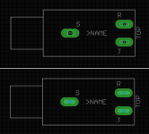
I'm trying to design a fooprint for a slim audio jack. I'd like to use oblong holes/slots instead of ordinary big holes but Eagle does not support oblong holes.
I've seen couple of solutions but I couldn't find a clear answer - which method is proven and working.

As for now I have two versions of the same footprint, both using milling layer for a slot shape. Version on the top - rectangle inside a solderpad . Bottom version - single line with appriopriate width (width of the slot).

Any tips?

1717099096894.png
 
so that cyan line is on the milling layer. I am terrible at drawing in Eagle (spoiled by Illustrator's bezier pen tool), but this is basically what you do, I used the arc tool and then you can use the line tool to connect it all to make a contiguous "line"

There seems to be a threshold for hole sizes vs milling, but I'm not sure what it is. The test file I uploaded to JLC shows this one works with 1mm drilled holes with the milling layer in cyan.
1717107110143.png

1717107292211.png

I tried it on some smaller holes (to have square holes for Du Pont connectors), but they did not show up at all in JLC's gerber viewer.


1717107249137.png
 
You'll also have to edit your diameter (not drill) of the pad to compensate. The pad on the right is "auto" diameter for the copper material, for reference, with the same 1mm drill size.
1717107467295.png

The shape is set to "long" fyi

Also, take this all as experiential, as I haven't had any of these examples fabricated yet, so your mileage may vary. I did all of this based on a few examples I found scouring the internet.

There may also be a need to use one of the built in scripts to make sure the trace/wire goes all the way through the pad material. I haven't gotten that far yet…
 
another thing I should note is that I'm terrible at drawing (might've said that already) in Eagle, but also, I tweaked the grid units to make it easier on myself—something like 0.1mm coarse and 0.02mm fine (alt)—and then switched it back to default
 
If this is for use with the 6.35mm slimline jacks like these, I have an Eagle footprint that I've used successfully with JLC and I'd be happy to share.
That's what I was building, but if you've got a working one I'd also like to grab it, if that's okay. I'd like to compare it so I can see how much I've screwed up haha.
 
so that cyan line is on the milling layer.
I also used milling layer in my example. But I took the easy way and drew a rectangle :)
You'll also have to edit your diameter (not drill) of the pad to compensate. The pad on the right is "auto" diameter for the copper material, for reference, with the same 1mm drill size.

With custom footprints I always set the pad diameter manually. I dont' use "auto" setting.

There may also be a need to use one of the built in scripts to make sure the trace/wire goes all the way through the pad material. I haven't gotten that far yet…
This is something new to me...

another thing I should note is that I'm terrible at drawing (might've said that already) in Eagle, but also, I tweaked the grid units to make it easier on myself—something like 0.1mm coarse and 0.02mm fine (alt)—and then switched it back to default

In these matters, I prefer object "properties" and entering coordinates manually. Sometimes you have to do some math, but at least it's precise.

If this is for use with the 6.35mm slimline jacks like these, I have an Eagle footprint that I've used successfully with JLC and I'd be happy to share.

It's for the same jack. I use Elecrow but I hope it won't be a problem. We'll find out soon. Thanks for the offer, I'll send you PM.
 
Back
Top