SOLVED Power Supply for Kliche Mini SE

wysiwyg

New member
Just finished building the Kliche Mini and have a question on the power supply behavior. I had an issue with the LED (CLR issue) which led me to check the power supply as part of debugging.

I'm seeing the following voltages on the charge pump IC (IC100):

1 7.9
2 4.55
3 0
4 -3.26
5 -7.7
6 2.97
7 4.38
8 7.9

The main input voltage is 9.03, but it drops 9.03 -> 8.77 across D100 and 8.77 -> 7.9 across R100. Is this normal? If not, any ideas what is happening? The pedal sounds fine and there is no signal loss when in bypass mode (Note: C5 is not installed...awaiting the part...but I'm ignoring for now since it is in the signal path).

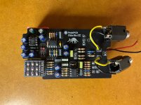
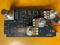
Here are some pics. Appreciate any help.
 

Attachments

  • IMG_1258.jpg
    IMG_1258.jpg
    501.3 KB · Views: 7
  • IMG_1262.jpg
    IMG_1262.jpg
    509.9 KB · Views: 7
Your component designators don't match the current build documents.

Can you please confirm which diodes/resistors you are talking about?

I honestly don't see anything wrong with any of the values you have posted though - yes, you will lose voltage over any series diodes/resistors from the power supply.
 
Thanks for the reply. I'm actually referencing the 'Special Edition' version of the Kliche Mini that has different/staggered knob placement. You'll see the D100 and R100 on that schematic.

And apologies for my poorly worded question. To your point, the voltage drops that I'm seeing across the 1n5817 and 100R make sense. But I'm not sure why they're in this particular circuit. I just checked the standard Kliche Mini (not the 'Special Edition') and even the schematic for the original design (I referenced Electrosmash) and these components are not present. At this point, I'm leaning toward replacing them with wire links but looking for any thoughts on why they're present before I replace them.
 
It could be that the charge pump is defective, perhaps with an internal short. +9VDC supply should render around +8.5VDC after the 1N5817 & 100ohm resistor.
The voltages indicate no voltage doubling and more current than designed, going across the diode and resistor, causing additional voltage drop.
I always socket ICs, and highly recommend it for charge pumps. as the ones available for hobby purchase are the most unreliable in my experience (typically audible switching frequency noise).
Pull the charge pump, ground its pin 5 and test the pedal without it. The measure at pin 1 should be 8.5 ish given a 9.0V supply. If it still measures low it may be the wrong values for R101 & R102, or one of the TL072's are drawing too much current.
 
At this point, I'm leaning toward replacing them with wire links but looking for any thoughts on why they're present before I replace them.

Proper reverse polarity and over-voltage protection.

A stock "Klon" will self-destruct in either case. You can lower the 100R (or jumper it if you desire) but keep in mind it is the only thing limiting current through the 12V zener diode if/when reverse polarity is applied.
 
Thanks, makes perfect sense. I hate having 'exothermic reactions' in my pedals! Interesting as it seems there's no reverse polarity protection in the original design (and many adapters using center positive at the connector).

To the earlier post, I checked the current draw of the pedal and it's around 9 mA w/o the LED...seems ok. Also, the original design seems like an odd implementation of the charge pump and is pulling the 'doubled' voltage across a couple of 1N4001 diodes. I'm seeing about 14.7v at that point which would seem to correlate with the lowered supply voltage.

Many thanks for everyone's help.
 
Back
Top