Not sure what you're thinking here, nor what you mean to say.
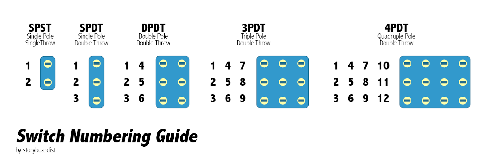
Lug numbering on switches is in columns or poles and the connections are made up and down NOT side-to-side:
View attachment 85343
1 4 7
2 5 8
3 6 9
You've already been given lowpitch's diagram in post #4. If you have a 3PDT stomper, use two of the poles (ANY two poles) and leave the other pole empty...
Here, instead of explaining it, I whipped up a diagram where you can use your common-anode LED as well:
View attachment 85345
Oh, I see lowpitch has addressed the numbering while I was messing with the graphic in DIYLC ...
ANyHooHah... If you want an EXTRA GAIN POT, I can show you how to have two separate gain pots (would require offboard wiring the current gain-pot / or two different master volumes if you prefer) when you switch between the two "structure" settings — WITH LED indication, but you'd need to order an
4PDT on-on stomper.
Having the extra gain pot or vol pot would allow you to compensate for when the structure switch is thrown. (In fact, if you did two different gain pots, you could GET RID of STRUCTURE and wire up both pots and an LED with a regular
3PDT stomper.
PS: The 4k7 CLR in the diagram is arbitrary, use whatever CLR-value gets the brightness desired from the Bicolour LED.


