PPCB Complex OD Footswitchable mode (?)

cris_mas

Active member
Well, that, i seem to understand i can use a dpdt footswitch to make modes more usable in a live context, but i want to implement a bi color led to know the status of which side i'm using and i kind of not know how to do that.

If anyone can help me with indications or a drawing i would appreciate that. Bear in mind i don't have too many electronics skills lol.
Thanks in advance!
 
If all you need is a dpdt to select the mode, then use a 3pdt switch with the 3rd piece to control which lead of the LED to connect. Whether anode or cathode depends on what LED you have. You'll have to offboard wire the switch.
 
If all you need is a dpdt to select the mode, then use a 3pdt switch with the 3rd piece to control which lead of the LED to connect. Whether anode or cathode depends on what LED you have. You'll have to offboard wire the switch.
so, what i understand is that i have to use the control lead of the pcb to operate the status lead as i normally should right? so the idea is to use the stomp dpdt instead of a normal switch spdt to "see" whether im using the low gain mode or the high gain mode. Actually that's practical so i would just use one bicolor LED to set status and mode, right?
 
can i get away the mod with this spdt? I've ordered the wrong part.
DANG IT!
WhatsApp Image 2024-11-08 at 21.19.36.jpeg

Also, i've been sold on (apparently) fake TL072's:
WhatsApp Image 2024-11-08 at 21.23.19.jpeg

It was supposed to be a happy weekend 🥲
1731111966470.png
 
If you can get other switches I would recommend it. Those "X-wing" switches fail quite readily and also melt very easily if you're not careful when soldering.
 
That is a bummer about the ICs. Where did you get them?
You can wire the switch without the LED, just the wires from the PCB.
from a local supplier. My usual supplier runed out of original TI TL's.
I've talked to the guy and i think he will send me some he had somewhere, but i'm still in need of the switch and Bi color led, so i'll have to wait anyway
 
This might be my final post in this topic. I’m running out of patience. Turns out my stupid head forgot to buy a dpdt switch, and the only LED I could find was common anode. I will postpone this mode and will build it the regular way.
I was thinking in using a 3pdt instead a dpdt but was wrapping my head around how to do so, because I have a row of pins that works as a “wall” between the outer pins (pins 1,4,7 and 3,6,9) so to “bridge” them I would have to use the center ones… but like i said before, not having the chance of having common cathode LED reduces my original plan to 0.
The good news is I’ve found the TL072, my supplier gave me one and I had 3 in my electronic parts box. I also have NE5552’s and the fake TL072’s. With the sockets, I’ll try them all. Thanks for all the help, once again dear forum.

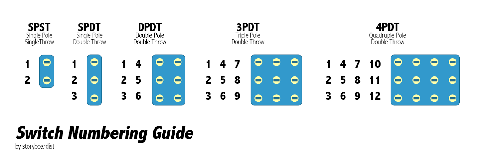
First of all check out this image:
Switch%2BNumbering%2BGuide.png

Now for the rest. You can use common anode LED without issues. Just connect the anode leg of the LED (middle and longest leg) to the A pad on the PCB and wire the two cathode legs (the shorter outside legs) to the outside lugs of the switch (1 and 3 for example if we're using the numbering from the image). Then solder a wire from the middle lug of the switch (lug 2) to the K pad on the PCB.
You can use a 3PDT and just ignore the third column of lugs (7, 8, 9). The switches above connect the middle lug (2, 5, 8, 11) of each column to either of the outside lugs (2 and 1/3, 5 and 4/6, etc.) of the same column.
 
...
I was thinking in using a 3pdt instead a dpdt but was wrapping my head around how to do so, because I have a row of pins that works as a “wall” between the outer pins (pins 1,4,7 and 3,6,9) so to “bridge” them I would have to use the center ones… but like i said before, not having the chance of having common cathode LED reduces my original plan to 0.
...

Not sure what you're thinking here, nor what you mean to say.

Lug numbering on switches is in columns or poles and the connections are made up and down NOT side-to-side:

3PDT switch throws.jpg


1 4 7
2 5 8
3 6 9


You've already been given lowpitch's diagram in post #4. If you have a 3PDT stomper, use two of the poles (ANY two poles) and leave the other pole empty...


Here, instead of explaining it, I whipped up a diagram where you can use your common-anode LED as well:

SWITCH SOLUTION FOR CRIS_MAS.png


Oh, I see lowpitch has addressed the numbering while I was messing with the graphic in DIYLC ...


ANyHooHah... If you want an EXTRA GAIN POT, I can show you how to have two separate gain pots (would require offboard wiring the current gain-pot / or two different master volumes if you prefer) when you switch between the two "structure" settings — WITH LED indication, but you'd need to order an 4PDT on-on stomper.

Having the extra gain pot or vol pot would allow you to compensate for when the structure switch is thrown. (In fact, if you did two different gain pots, you could GET RID of STRUCTURE and wire up both pots and an LED with a regular 3PDT stomper.


PS: The 4k7 CLR in the diagram is arbitrary, use whatever CLR-value gets the brightness desired from the Bicolour LED.
 
thanks guys, sorry for the drama queen post above, i'm just a bit frustrated beacuse i'm having problems for parts sourcing and also i'm doing things beyond my knowledge on electronics. Apart from that, i'm repairing a Floyd Rose guitar (hate this bridges lol :ROFLMAO: ) and having a belated job report summed to head ache i'm a mess right now. Later i will apply your phenomenal tips!
thanks guys!
 
Not sure what you're thinking here, nor what you mean to say.

Lug numbering on switches is in columns or poles and the connections are made up and down NOT side-to-side:

View attachment 85343


1 4 7
2 5 8
3 6 9


You've already been given lowpitch's diagram in post #4. If you have a 3PDT stomper, use two of the poles (ANY two poles) and leave the other pole empty...


Here, instead of explaining it, I whipped up a diagram where you can use your common-anode LED as well:

View attachment 85345


Oh, I see lowpitch has addressed the numbering while I was messing with the graphic in DIYLC ...


ANyHooHah... If you want an EXTRA GAIN POT, I can show you how to have two separate gain pots (would require offboard wiring the current gain-pot / or two different master volumes if you prefer) when you switch between the two "structure" settings — WITH LED indication, but you'd need to order an 4PDT on-on stomper.

Having the extra gain pot or vol pot would allow you to compensate for when the structure switch is thrown. (In fact, if you did two different gain pots, you could GET RID of STRUCTURE and wire up both pots and an LED with a regular 3PDT stomper.


PS: The 4k7 CLR in the diagram is arbitrary, use whatever CLR-value gets the brightness desired from the Bicolour LED.
There's an onboard CLR already (R107), so no resistor needed between switch and PCB, other than that yes to everything :D
 
True, but R107 is for the bypass-indicator LED, which might require a different brightness;
You could wire up the STRUCTURE LED to the ground of the bypass switch, so it does double duty as the bypass-indicator, but I'd keep the BYPASS and the STRUCTURE separate as I'd want to know beforehand when turning the pedal on which mode of STRUCTURE it was in.
oh, i get what you're saying, thing is I'm using a switcher so i leave the pedals on anyway, so it's more useful to know if structure is engaged or not, and if that also serves the purpose of showing the pedal is "on", it's perfect for me.
 
Well, I've managed to build the pedal successfully but I've noticed that the bottom 2 leds aren't emitting light (barely), so 'im not sure if i did something wrong or is normal, structure switch works as expected, gives a bit more "oomph" to the tone and a bit more gain and volume (nice stuff by the way, way more useful than putting the switch on a mini configuration IMHO).

Now i have to drill the "custom" enclosure and see what will the outcome be.
Thanks forumites!
 

Attachments

  • WhatsApp Image 2024-11-17 at 13.56.22.jpeg
    WhatsApp Image 2024-11-17 at 13.56.22.jpeg
    244 KB · Views: 5
Back
Top