

OD is Glorious
Well-known member
- Build Rating
- 4.00 star(s)
I have built a few PPCB Mufflers byt these PPCB Muzzle’s are in another league. I would say the Muzzle is not just better than the Muffler, it is significantly better. The dual green/red LED is a yellowish color when the gate closes and green when open. There is no sputtering, no harsh cut, and no sagging like the PPCB Muffler circuit. The Muzzle also does not have that confounding counterclockwise sensitivity like the PPCB Muffler. The Muzzle is a proper noise gate and I will for sure build another in a 1590b without key jacks (because I do not think they will fit). I see quite a few comments from Muzzle builders who struggled with the key jacks so maybe detailing my own mistakes here can help someone. If you like noise gates like I do, you may want to build a Muzzle.
Build report
The circuit was easy to assemble and the parts are available, with the exception of the THAT4301. This circuit worked great upon completion, and then I began to bungle the build with some ham-fisted key jack stupidity. I feel like the BOM should have a large stop sign on the key jack section. STOP – learn what a key jack is and what a switched tip jack is, and how to identify connections, and make sure your key jacks are grounded. I also could have used a diagram to show me how to use Key jacks along with top jacks.
I plowed ahead not knowing what a key jack was, or a “switched tip jack”. I initially soldered in two enclosed mono key jacks not realizing I needed “switched tip key jacks”. DOH! SHORTED! The components on the board immediately got HOT! I then read a few comments on the forum and elsewhere and I learned about switched tip jacks. My pricey THAT4301 got very hot and the pedal stopped working so I replaced many of the components. I ordered two more NOS THAT4301s. If you are building one you might consider the PPCB retrofit THAT4301 which is half the price of a NOS THAT4301.
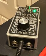
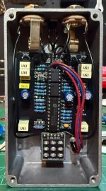
Out of caution, I tossed the LT1054 charge pump, the TL072, all diodes and the three 100u capacitors. Also I will note here that the common cathode LED was burned out on the red side so I also replaced it. Thankfully with the new THAT4301 I was able to test the circuit and confirm that the original THAT4301 was still good! So after replacing the other parts I ran a jumper across the key jack terminals for testing and the circuit worked great again. So then I ordered some switched tip jacks… they were in fact switched tip jacks and I used a multimeter to identify the switched tip (see below). But after installation and boxing the key jacks hissed and had interference. So I unboxed and went back to troubleshooting… I then realized I had used Peavy Insulated switched tip jacks – could it be that they needed to be grounded? Short answer is yes because I grounded them both and the pedal’s key jacks worked great with no noise. FYI: the BOM calls for the key jacks to be above the PCB but I put them underneath.
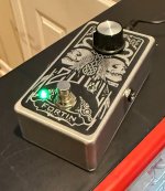
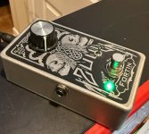
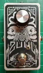
The case is a bare aluminum with matte clear and it has a film free label which was then top coated with 2k matte clear. The decal is a copy of the original ZUUL. The BOM calls for a mini slide SPDT but I used a sub-mini Taiway switch which I mounted in a female pin header so it would reach outside the case. The main jacks are Switchcraft and the main footswitch is a soft click. I used a PPCB top jack plate. Here is a link to the old skool Big knob I used from Stompbox.
Some notes about this circuit and “switched tips”

Build report
The circuit was easy to assemble and the parts are available, with the exception of the THAT4301. This circuit worked great upon completion, and then I began to bungle the build with some ham-fisted key jack stupidity. I feel like the BOM should have a large stop sign on the key jack section. STOP – learn what a key jack is and what a switched tip jack is, and how to identify connections, and make sure your key jacks are grounded. I also could have used a diagram to show me how to use Key jacks along with top jacks.
I plowed ahead not knowing what a key jack was, or a “switched tip jack”. I initially soldered in two enclosed mono key jacks not realizing I needed “switched tip key jacks”. DOH! SHORTED! The components on the board immediately got HOT! I then read a few comments on the forum and elsewhere and I learned about switched tip jacks. My pricey THAT4301 got very hot and the pedal stopped working so I replaced many of the components. I ordered two more NOS THAT4301s. If you are building one you might consider the PPCB retrofit THAT4301 which is half the price of a NOS THAT4301.
Out of caution, I tossed the LT1054 charge pump, the TL072, all diodes and the three 100u capacitors. Also I will note here that the common cathode LED was burned out on the red side so I also replaced it. Thankfully with the new THAT4301 I was able to test the circuit and confirm that the original THAT4301 was still good! So after replacing the other parts I ran a jumper across the key jack terminals for testing and the circuit worked great again. So then I ordered some switched tip jacks… they were in fact switched tip jacks and I used a multimeter to identify the switched tip (see below). But after installation and boxing the key jacks hissed and had interference. So I unboxed and went back to troubleshooting… I then realized I had used Peavy Insulated switched tip jacks – could it be that they needed to be grounded? Short answer is yes because I grounded them both and the pedal’s key jacks worked great with no noise. FYI: the BOM calls for the key jacks to be above the PCB but I put them underneath.
The case is a bare aluminum with matte clear and it has a film free label which was then top coated with 2k matte clear. The decal is a copy of the original ZUUL. The BOM calls for a mini slide SPDT but I used a sub-mini Taiway switch which I mounted in a female pin header so it would reach outside the case. The main jacks are Switchcraft and the main footswitch is a soft click. I used a PPCB top jack plate. Here is a link to the old skool Big knob I used from Stompbox.
Some notes about this circuit and “switched tips”
- Tight It is tight up top and I do not think enclosed jacks will work for the main jacks. YMMV.
- Sub mini- the exterior mounted SPDT switch should probably just stay inside the enclosure - no need to expose it
- Great without key jacks the pedal is terrific without key jacks, so just jumper the inner and outer holes in the key jacks section of the PCB if you do not want to mess with the key jack situation.
- Identifying the Switched tip (my jack has four possible connections)
- How to verify in seconds with a multimeter:
- Set your multimeter to Continuity mode (beeping mode) (or Resistance/Ohms):
- With no plug inserted: Put one probe on the main tip leaf spring (or main tip pin) and test the remaining pins. The pin that beeps is your switched tip.
- Insert a 1/4" plug: The continuity between the tip pin and the switched tip pin should immediately break (no beep).
- Finding the Ground on your jack with a multimeter
- Plug a standard 1/4" TS cable into the jack.
- Set your digital multimeter to the continuity (beeping) mode.
- Touch one probe to the outer metal sleeve (the bare part of the plug at the other end of the cable) and touch the other probe to each solder lug on the jack until you get a continuous beep. That matching lug is your ground
- Robert told me a quick test method for key jacks after installation;
- Guitar > Key Input
- Key Output > Pedal Input (patch cable)
- Pedal Output > Amp Input
Attachments
Last edited:
