Hey, first post on the forum and first Pedal PCB build!
I recently finished building the Low Tide Modulator from a kit from musikding.de. Everything seemed fine, power not shorted, presumably correct voltages on the IC sockets (before plugging in the chips), and the LED gets power. But when I finally started testing with audio, there was no sound when the footswitch was in active mode, while bypass worked.
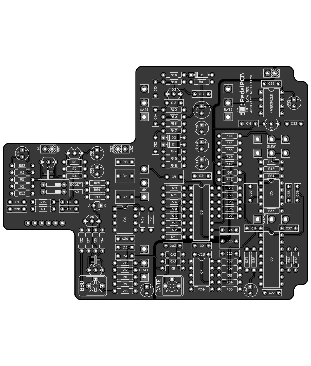
I started checking the continuity between different parts of the circuit, and I noticed that the tip and sleeve (audio in and ground) are shorted when the switch is in the on mode. I think I might have connected the switch incorrectly. The kit came with the 3PDT Breakout Board (https://www.pedalpcb.com/product/pcb126/), while the build instructions specify connections straight to the switch pins. I assumed that the breakout board should be connected in the same order as the holes on the main PCB, see pictures, but I might be wrong here?
If someone could confirm what the order of the holes on the Low Tide PCB is, I would be very grateful!
And it would be nice to know what the V+ and V- voltages on the chips should be, my readings on LM13700N were slightly strange (quite close to each other).

I recently finished building the Low Tide Modulator from a kit from musikding.de. Everything seemed fine, power not shorted, presumably correct voltages on the IC sockets (before plugging in the chips), and the LED gets power. But when I finally started testing with audio, there was no sound when the footswitch was in active mode, while bypass worked.
I started checking the continuity between different parts of the circuit, and I noticed that the tip and sleeve (audio in and ground) are shorted when the switch is in the on mode. I think I might have connected the switch incorrectly. The kit came with the 3PDT Breakout Board (https://www.pedalpcb.com/product/pcb126/), while the build instructions specify connections straight to the switch pins. I assumed that the breakout board should be connected in the same order as the holes on the main PCB, see pictures, but I might be wrong here?
If someone could confirm what the order of the holes on the Low Tide PCB is, I would be very grateful!
And it would be nice to know what the V+ and V- voltages on the chips should be, my readings on LM13700N were slightly strange (quite close to each other).