GizzWizzKing
Well-known member
- Build Rating
- 5.00 star(s)
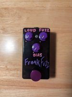
The Fuzzly Bear is a Bosstone with a Bias control and double the diodes, which fixes the low volume of the original and allows me to get nearly infinite fuzz tones out of it. If you build one I suggest using all logarithmic pots because the gain and the bias come on strong quick. For me it would be nice to hang out in the lower range for more of the sweep of the control. With the gain in the upper half of the sweep the fuzz gets pretty bloated and blown out sounding. But then using your guitar controls and/or the bias can bring it back into usable unique sounds. Top tier vintage style fuzz. Great synthy sounds too and hints of octave in the upper portion of the fretboard.
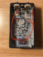
This enclosure started its journey in early 2022. The Teddy Rupture PCB was one of my first PPCB attempts. I did pretty poorly. Eventually I salvaged the enclosure and ended up putting a vero fuzzly bear in it. But that was also not very good and eventually developed intermittent issues. So here we are with another iteration in the same enclosure. Now featuring labels.
PtP is pretty zen. I suggest trying it.
I learned about LEDs a bit this build. I generally test the LED quickly on my bench in the circuit before mounting. For that I use a 9v and battery snap. Tested and worked. So I soldered it in early on in the build and then everything fell in on top. When I want to test it on my board with my power supply the LED did not light but the circuit worked. DOH! but... I tested it... So I walked back over and used the 9v snap and.... It worked... What...?
Color me confused. Turns out I had the LED backwards and I guess because I installed the anode side to the 9v supply and the CLR on the cathode somehow the LED would light but only with a battery. Plugged it into power and poked around with an LED and put it all back together.