SOLVED quick question pcb mount 9v barrel jacks

comradehoser

Well-known member
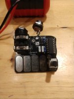
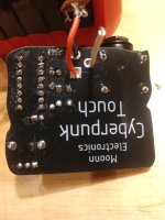
Built the Moonn "Cyberpunk Touch" and "Drone a Little Drone", but forgot to order pcb mount barrel jacks. So, I just soldered in some wires from a regular 9v enclosure jack to the PCB jack pads, ground to the round pad in front, and hot to the square pad in back. Didn't bother with the switch lug on the side.

Problem is that I get ticking and no signal. So what am I missing in the difference between a regular 9v jack and a board mount 9v jack?

The same ticking and no signal happened on my last batch of Moonn boards when I inadvertently introduced 9V into the ground (I think) by directly connecting the 9v supply with the LED ground on the 3pdt. So somehow I'm getting a 9V/ground path? Is it necessary to cut the trace from switch pad to the ground pad? I tried connecting switch prong on the jack to switch pad, same problem.

It's definitely not a fault in my assembly besides the 9v. I found external +/- pads on the Drone PCB, and after soldering things there, it worked, but initially it was exactly the same problem.
IMG_20250825_200650232.jpg IMG_20250825_200725506.jpg
 
Solution
hah, thanks for reminding me why I switched to using PCB mounted jacks in the first place. I'm like 90% sure that you've reversed the polarity.
Every damn time I try to solder one of these I have to look up the pinout and I still get it wrong.

Not sure which jack is supposed to go in there, but this:
shows that pin1 (the square pad where you have the red wire connected) goes to center (which on a pedal supply is ground).
 
Solution
What do you measure for voltages on the 556 when it's plugged in?
Looks like pin 14 (top right) should measure 9V and pin 7 (bottom left) is ground.

Also it looks like the reverse polarity protection in this circuit just creates a short circuit between
+9/GND if it's reversed, so I imagine that could damage the diode (or power supply!) over time.

You could also use the continuity tester of your meter based on those pins - which of those
pads really is connected to GND and 9V?
 
I couldn't access your link, by the way.

continuity: square pad does connect to the anode end of the 4001 diode, ground to the cathode/stripe end. Everything current flow seems as it should, but I still get ticking and no signal. It's a good idea to do a voltage probe to see if in fact I'm getting 9v on the ground, though, so that's an idea.

I'll check the 556 when I get home but I doubt it's the issue, just from the consistency of the problem between the two boards and the resolution of one by connecting via another way. I'm almost certain it's something super basic I'm missing in my ignorance related to the board and jack arrangement.

The real solution is to order a dang board-mount barrel jack, but I HATE one-off ordering and I am too impatient to see what this sounds like.
 
hah, thanks for reminding me why I switched to using PCB mounted jacks in the first place. I'm like 90% sure that you've reversed the polarity.
Every damn time I try to solder one of these I have to look up the pinout and I still get it wrong.

Not sure which jack is supposed to go in there, but this:
shows that pin1 (the square pad where you have the red wire connected) goes to center (which on a pedal supply is ground).
This was it after all. I think when I tried reversing it, I was holding the board in a way to short the chip so it didn't make any sound. Duh!

I looked at the traces on the drones board that was working, and sure enough, the positive went to the cathode/band side and the negative to the anode side. The opposite of what I'm used to with pPCB circuits. I'm guessing instead of sacrificing a 5817, this power protection catches it into a loop to ground.

Long story short, I switched it again, and this time it worked.

Fun little board, I have to say.

Thanks, Bud!
 
I'm guessing instead of sacrificing a 5817, this power protection catches it into a loop to ground.

Yeah the build doc has the schematic and that's right, it's straight to ground. Kind of surprising to make the ground protection be a dead short. Most of the time when you design a circuit like that, you want to add a (poly)fuse that would trip.

Glad to hear your build is working, it looks neat!
 
Back
Top