bilisnegra13
Member
Hello folks
I need a reverse engineer, tracing master
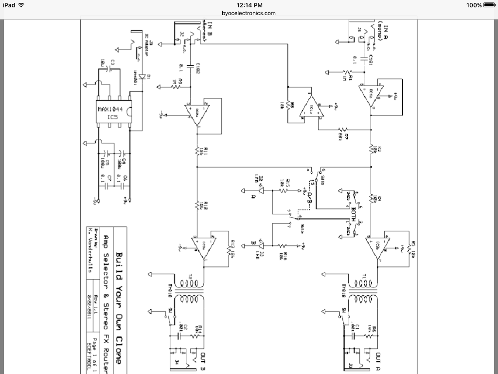
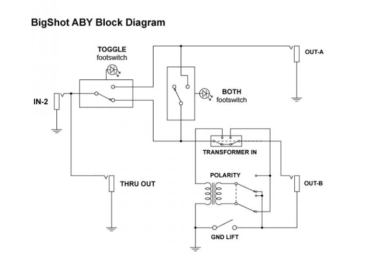
Since my skills for doing schematics from scratch are bad I come here and ask if anyone can help with that, plus checking if all connections makes sense and to see if anyone can find the transformer substitute for this one since typing the numbers on the trafo on the web, doesn't show any successful results
Black traces are GND
RED traces are top layer and BLUE traces are Bottom layer
Electrolytic cap is non polarized
Thanks in advance
I need a reverse engineer, tracing master
Since my skills for doing schematics from scratch are bad I come here and ask if anyone can help with that, plus checking if all connections makes sense and to see if anyone can find the transformer substitute for this one since typing the numbers on the trafo on the web, doesn't show any successful results
Black traces are GND
RED traces are top layer and BLUE traces are Bottom layer
Electrolytic cap is non polarized
Thanks in advance