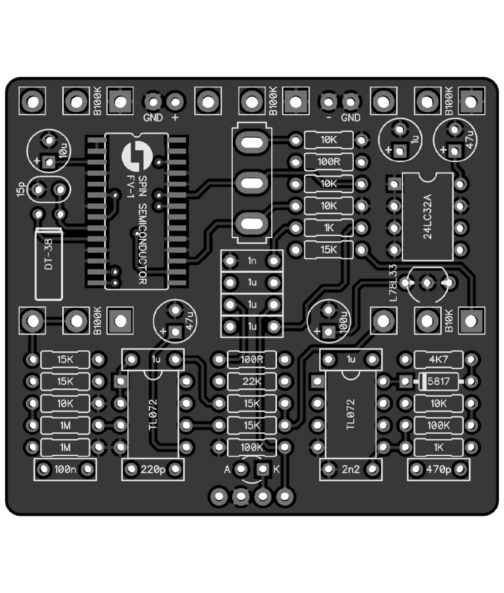
Radium Springs: Tweak values/trimpot For Tremolo Level?

Bucksears

Well-known member
I read the review of the Radium Springs where a user tweaked some resistor values to adjust the tremolo level, when using those modes:
"replace the resistors controlling the tremolo signal with trimpots using the handy Trimmit boards or socketing them and changing them out until you like them."

Anybody know which resistors those are?
Thx!
 
Changed my mind about the direction for this board and ordered the EEPROM for the ThreeVerb, but still curious about the above changes.
 
Changed my mind about the direction for this board and ordered the EEPROM for the ThreeVerb, but still curious about the above changes.
All the parameters for the tremolo section are in the EEPROM that contains the FV-1 algorithms. And as such, there are no external component values that can be changed to affect the tremolo or other settings. It's all in the code found in the EEPROM. That's why there has never been an answer for tweaking the resistors of a Radium Springs to alter the tremolo signal.
 
I read that review as well and it is not super obvious what was done. After looking at the schematics, and if I was to build this, I would replace each of R7 and R16 10k resistors with either a 20k trimpot, and use middle leg an one of the outer, and cut the other outer. Probably best with legs that make up 0-20k rather than 20k-0k going clockwise. Might have added a 1k in series with the trimmer to avoid any zero k situation by mistake during tweaking.
Or as the reviewer wrote, use the trimmer until you have what you like and put in a fixed closest value instead. Might not be likely to return to tweaking. But if that is the case, consider 20k Lin (B) pots and drill 2 more holes instead, but it sounds more like a "tweak until you like" rather than "let's tweak again" scenario.
 
R7 and R16 are pull-down resistors for the mode switch. Their values are irrelevant as long as they are high enough to not load the 3.3V supply and low enough that the pins still return to near 0V when open. Changing them wouldn't affect the sound.

Like @Cybercow said, this is a mostly digital circuit. There's not much you can do to modify the tremolo or reverb aside from maybe some filtering or throw off the mix. (Which would be pointless since there's a Wet/Dry mix control)
 
Just finished the build today, sounds great as Spring Reverb :-)
I assumed that R7 and R16 were involved in the tremolo part, so I socketed them and put in a 1k + 20k trimmer as mentioned.
Finding the proper mod with the switch and turning the trimmer did not really produce anything as far as I could tell, just as Robert wrote.
Not really sure what was meant in the review on pedalpcb.com for the Radium Springs as OP quoted.
I did not feel anything untoward regarding the trem so I'll stick with the 10k fixed values.
 
Just finished the build today, sounds great as Spring Reverb :-)
I assumed that R7 and R16 were involved in the tremolo part, so I socketed them and put in a 1k + 20k trimmer as mentioned.
Finding the proper mod with the switch and turning the trimmer did not really produce anything as far as I could tell, just as Robert wrote.
Not really sure what was meant in the review on pedalpcb.com for the Radium Springs as OP quoted.
I did not feel anything untoward regarding the trem so I'll stick with the 10k fixed values.
What the reviewer wrote is just wrong. Changing the values of those two resistors will do nothing. The three switch control inputs (pins 16, 17 & 18 - of which 16 & 17 are connected to R7 & R16) are digital in nature - On or Off; being either 3.3V or Ground. You did well to sort out that the 10K R6 & R17 values are good.
 
What the reviewer wrote is just wrong. Changing the values of those two resistors will do nothing. The three switch control inputs (pins 16, 17 & 18 - of which 16 & 17 are connected to R7 & R16) are digital in nature - On or Off; being either 3.3V or Ground. You did well to sort out that the 10K R6 & R17 values are good.
Thanks.
So are we sure that the R7 and R16 are the tremolo candidates mentioned?
I agree that using R7 & R16 as the Resistors mentioned is wrong, but it nags me that the review referred to something actually done with a trimmer...
...and that affected the trem effect.
4th review from 2021
 
Thanks.
So are we sure that the R7 and R16 are the tremolo candidates mentioned?
I agree that using R7 & R16 as the Resistors mentioned is wrong, but it nags me that the review referred to something actually done with a trimmer...
...and that affected the trem effect.
4th review from 2021
I do not believe it actually effected the tremolo in any way except to change the patch. The activity on the FV-1's pins 16, 17 & 18 only has bearing with algorithm (patch) selection. I'm reasonably sure the reviewer didn't understand the schematic.
 
I do not believe it actually effected the tremolo in any way except to change the patch. The activity on the FV-1's pins 16, 17 & 18 only has bearing with algorithm (patch) selection. I'm reasonably sure the reviewer didn't understand the schematic.
Ok, thanks.
And the tremolo is only affected on the pins, pots and Resistor we have mentioned, right?
 
Ok, thanks.
And the tremolo is only affected on the pins, pots and Resistor we have mentioned, right?
No. The tremolo is ONLY affected by the design of the algorithm (patch) in the EEPROM. All the pins, pots and resistors are just a means of accessing any specific algorithm (patch) in the EEPROM.

In a typical FV-1 circuit, there are up to three pots designated to manipulate the editable parameters in any given algorithm. They are able to "reach inside the patch" and change values of the perameters given such access. The other controls are usually set up as Volume and Mix - completely external to the FV-1.
 
Back
Top