RGB LED with DPDT Footswitch

Hello all,

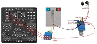
I have what is hopefully a quick question. I am building the Taqueria Overdrive, and I am modding the gain toggle to use an RGB LED with a DPDT Footswitch (Blue for normal, Red for High Gain) I got the idea from Reddit, but it seems the user made it more complicated than it needs to be. Can I just wire lug 5 of the DPDT to the anode pad and the common cathode of the RGB LED to the cathode pad? I'm using a 3PDT Breakout board. I assume I wouldn't need an LEDR either in this case as CLR is already in the circuit.
bolt-v0-bgunuk7wtxie1.webp
 
1) I know you didn't ask but I prefer common cathode for these uses. Better to switch ground, imo. No risk of shorting 9v to your in or out jacks.
2) whichever common you have, connect your common LED to the corresponding LED leg on your breakout. Use the onboard clr, though the brightness may be different between the two setting.
3) take the other LED pad, let's you have a common cathode, take the cathode LED pad on your breakout to the center lug of you gain switch. Tie your 2 anodes to the top and bottom lugs.
Main switch should still switch the led on/off and the gain switch will alter gain.
This is the simplest way to go about it but you won't have any indicator of which way the gain is switched until you engage the pedal.
If you want an always on indicator, you'll just tie the common anode or cathode to vcc/ground and add a clr. Then switch the uncommon leg with the gain switch. Don't use anything from the main circuit for the gain indicator but add the on/off led as normal. Then you have 2 indicators including a always on gain indicator.
 
1) I know you didn't ask but I prefer common cathode for these uses. Better to switch ground, imo. No risk of shorting 9v to your in or out jacks.
2) whichever common you have, connect your common LED to the corresponding LED leg on your breakout. Use the onboard clr, though the brightness may be different between the two setting.
3) take the other LED pad, let's you have a common cathode, take the cathode LED pad on your breakout to the center lug of you gain switch. Tie your 2 anodes to the top and bottom lugs.
Main switch should still switch the led on/off and the gain switch will alter gain.
This is the simplest way to go about it but you won't have any indicator of which way the gain is switched until you engage the pedal.
If you want an always on indicator, you'll just tie the common anode or cathode to vcc/ground and add a clr. Then switch the uncommon leg with the gain switch. Don't use anything from the main circuit for the gain indicator but add the on/off led as normal. Then you have 2 indicators including an always on gain indicator.
Thanks so much for the response. Question regarding the last part about an always on indicator. Are you saying I’d add a second LED, one indicating if the switch is in bypass or not and another for the gain toggle tied directly to + and - (with a CLR)?

And just to clarify, the 3PDT Breakout Board I have doesn’t have an onboard LED. The LED has a common cathode.
 
There's a few options here. Let's make a choice first.
Do you want:
A)one LED that indicates gain setting but is only on when the pedal is engaged?
B) 2 indicators,/LEDs --one power one gain with the options:
B1) gain indicator always on
B2) gain indicator only on when pedal is on.
 
There's a few options here. Let's make a choice first.
Do you want:
A)one LED that indicates gain setting but is only on when the pedal is engaged?
B) 2 indicators,/LEDs --one power one gain with the options:
B1) gain indicator always on
B2) gain indicator only on when pedal is on.
It would be awesome to do option B1 at a later time, but I think I’d rather have one LED to indicate on/off and gain settings for this one.

From what I’m understanding and the very basic breadboarding I just did, I need resisted power going to the middle lug from the anode pad, and the cathode to the cathode pad. Does that sound correct? I’m okay if the brightnesses are a bit different, I think I’ll sub a 2.2k resistor instead of a 4.7k so they’re both brighter anyway.
 
It's really easy, just build the second footswitch to mimic the function of the toggle, then on its second set of poles, that's where you put your LED wires. First, you want to remove one leg of the LED CLR and solder a wire to it (in practice this means use a new resistor). That wire will now go to the center lug of the switch poles we were talking about earlier. Then make two wires, one from each outside pole, and make them go to the LED. We are going to use a common cathode bicolor for this. After that, take the LED's ground wire and feed it into the vacant solder pad of the CLR.

This makes it so the pedal's bypass indicator is also the gain select indicator. I did this with a LGSM to indicate silicon clipping vs LED's - green for Si and blue for LED.

If you want the gain select indicator to be independent, that's easy too, but you need to run a positive wire from the jack or any 9v+ source direct to one of the the center poles of the gain select foot switch. Be sure to install a CLR. Then run the other two wires to the LED. Again, using a common cathode. After that, run the LED's ground to any grounding point.
 
Last edited:
Back
Top