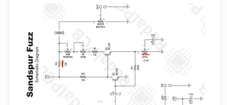
Sandspur Fuzz (Analogman Sunface) 1590a & 125b Builds

petercan

Member
Build Rating
5.00 star(s)
I was always a fan of this silicone fuzz face and threw one together with a BC108. I loved it so much I fiddled with it, saw something on this forum about increasing the value of R4 to increase overall output and tried that, and just played with the bias and clean trimmers to get different sounds. Overall, love this circuit and it’s my favorite type of fuzz.

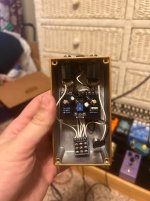
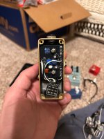
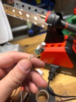
I built the 1590a pedal with BC108B transistors. It was tough to fit everything in there, but I took some clues from how @OD is Glorious did his and I got it in there. The only bad part about this build was I used a B1k 9mm pot for fuzz instead of C because that’s all I could find with the short pin legs. I tried to take a PCB mount pot and cut the legs but I royally screwed it up. I increased R4 to 1k to help with output and biased Q2 to 4.3V. Rolled the clean trim pot back to about 10:00 and it sounds beautiful.

Built the 125b pedal with BC109 transistors because “that’s what Gilmour used”, but I really don’t hear a difference between it and BC108. I did take the clean trimmer pot out to an external B50K pot and that is really helpful for playing with tone. I increased R4 to 680r and biased to 4.5v. Sounds killer, but I do have to roll the volume pot up way more on this pedal. I’ll leave R4 at 1k next time.

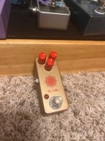
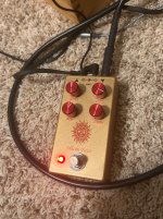
Both pedals enclosures are the tomic gold from Stompbox parts with a clear label graphic, tried to pay homage to the sunface. I sourced all my parts from Stompbox parts except for the A250k 9mm pot with was from Smallbear
 

Attachments

  • IMG_9619.jpeg
    IMG_9619.jpeg
    1,015.1 KB · Views: 18
  • IMG_9618.jpeg
    IMG_9618.jpeg
    646.5 KB · Views: 16
  • IMG_9620.jpeg
    IMG_9620.jpeg
    836.2 KB · Views: 19
  • IMG_9617.jpeg
    IMG_9617.jpeg
    640.1 KB · Views: 18
  • IMG_9616.jpeg
    IMG_9616.jpeg
    524 KB · Views: 19
  • IMG_9621.png
    IMG_9621.png
    391.4 KB · Views: 20
I like the graphic. I love to see you problem solving the way to fit it all. I like how you turned the trim pot into a potentiometer, Useful!

I just put one together yesterday. It is a fun circuit with a low parts count and high satisfaction count.

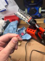
I can make one suggestion regarding the 9mm pot you chose. If you do it the way you did make sure to shrink wrap those soldered leads, or use one of these boards that Amplified Parts sells. I screenshot.

Keep up the good work
 

Attachments

  • Screenshot 2026-09-20 at 3.53.49 PM.png
    Screenshot 2026-09-20 at 3.53.49 PM.png
    559.2 KB · Views: 3
Last edited:
I like the graphic. I love to see you problem solving the way to fit it all. I like how you turned the trim pot into a potentiometer, Useful!

I just put one together yesterday. It is a fun circuit with a low parts count and high satisfaction count.

I can make one suggestion regarding the 9mm pot you chose. If you do it the way you did make sure to shrink wrap those soldered leads, or use one of these boards that Amplified Parts sells. I screenshot.

Keep up the good work
Thank you! That’s what i was looking for! I knew someone had to make those, I’ll have to get some.

Yes of course, I actually use the smallest heat shrink I could find (I think 1/16”) and put 1/8” over that right at the joint. Stiffens it up a bit
 

Attachments

  • IMG_9252.jpeg
    IMG_9252.jpeg
    491.8 KB · Views: 2
Beautiful looking builds.
I'm a little confused by the R4/biasing remarks. Are you saying you adjusted R4 to get it to a specific bias voltage at noon on the sundial/bias pot?
R3, R4 the bias pot and the sundial all set the bias.
R3 and R4 get you in the ballpark and the trimmer let's you dial it in.
From the the sundial/bias pot under/over biases.
Changing R4 from 1k to 680r is the same as turning the bias trimpot a 16th of a turn.
There is a slight change to the negative feedback but 420-530 ohms falls into -/-1% of the 33k R2. the idea behind the bias trimmer is to center the bias voltage on the sundial. Set it to 4.5-4.7 volts when the sundial is at noon.
Am I missing something?
Anyway. Way to squeeze em in there and great looking builds.
A little square of stripboard or tagboard can work on 9mm pots too.
I like to use a 3x3 square and loop the wire through2 holes. That way it doesn't slip out when I solder the pot on.
 
Beautiful looking builds.
I'm a little confused by the R4/biasing remarks. Are you saying you adjusted R4 to get it to a specific bias voltage at noon on the sundial/bias pot?
R3, R4 the bias pot and the sundial all set the bias.
R3 and R4 get you in the ballpark and the trimmer let's you dial it in.
From the the sundial/bias pot under/over biases.
Changing R4 from 1k to 680r is the same as turning the bias trimpot a 16th of a turn.
There is a slight change to the negative feedback but 420-530 ohms falls into -/-1% of the 33k R2. the idea behind the bias trimmer is to center the bias voltage on the sundial. Set it to 4.5-4.7 volts when the sundial is at noon.
Am I missing something?
Anyway. Way to squeeze em in there and great looking builds.
A little square of stripboard or tagboard can work on 9mm pots too.
I like to use a 3x3 square and loop the wire through2 holes. That way it doesn't slip out when I solder the pot on.
R4 does bias Q2, but it definitely helps with output. I don’t know circuitry well enough, i went to school for mechanical engineering so this stuff is hard for me to grasp. What I do is just play around with it and use my audio probe. I socketed R4 and my transistors on the first build I did and changed it from 100r to 4.7k. Output got louder each time, but affected the tone as it went up (got muddy and I couldn’t get the bias right after around 3k).
 
R4 does bias Q2, but it definitely helps with output. I don’t know circuitry well enough, i went to school for mechanical engineering so this stuff is hard for me to grasp. What I do is just play around with it and use my audio probe. I socketed R4 and my transistors on the first build I did and changed it from 100r to 4.7k. Output got louder each time, but affected the tone as it went up (got muddy and I couldn’t get the bias right after around 3k).

This is part of the old “mids” pot fallacy of the first wave of boutique Fuzz Face clones.

Any marginal bias shift from R4 is absolutely swamped by the increase in output volume.
 
This is part of the old “mids” pot fallacy of the first wave of boutique Fuzz Face clones.

Any marginal bias shift from R4 is absolutely swamped by the increase in output volume.
Care to expand? Seems more like darts in the dark. It's all attainable by adjusting either of the 2 variRs in series with R4. I expect the change in negative feedback is negligible. I suppose there's *some* impact. But a 32.7k vs a 33.3k R2 isn't dissimilar.
R4 does bias Q2, but it definitely helps with output.
I think you would have sensed the same change by turning the other 2 variable resistors. I'm too busy lazy to draw it out but resistances add up when in series. All 4 of those elements are in series between V+ and Q2. It doesn't matter electricaly which one increases or decreases.
To use the dumb and not accurate water metaphor:
Spigot(V+) to nozzle(Q2), every resistor is valve that restricted current. Completely ignoring the laws of fluid dynamics and not once considering head pressure or length or width of hose, you can restrict the current by increasing the resistance at any of the 4 valves. By restricting flow (current) you change pressure(voltage). VIR, ohms law etc.
The circuit is arranged so that valve 1 and 4 are fixed. In use you want valve 3 to sweep between minimum and maximum operating pressures (bias/voltage) for the user. to make it easy on the user, you adjust the other valve(bias trim) so that the user valve(sundial) is centered for the best flow/pressure relationship(4.5-4.7vdc). The user can then adjust the flow(resistance) with the valve(sundial) to change the pressure(bias) or Q2.
 
Back
Top