angelrulax
Member
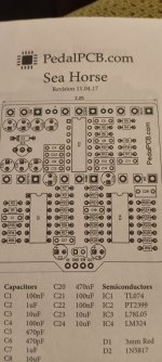
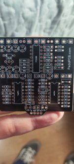
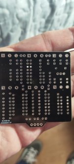
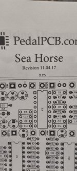
Hello, I've found an old Sea horse Pcb, which I bought in 2017 and I suspect is the v.1. Doing some researches in the forum I´ve seen there are two basic mods apparently to fix a bad schematic :
-Remove C19 (47nF) and put a 10nF cap between pin 1 and 2 of the LM324. OK, no problem with this.
-Cut a trace between INT lug 3 and left side of R31and add a jumper between this lug and right side of R31. Here is the problem or I'm completely wrong.
Doing a test with my dmm with that jumper in my old PCB INT lug 3 goes to pin 6 of the LM324, but in the schematic of the latest version of the PCB INT lug 3 goes to C15 negative side. Can anybody help me? I attach some images.
Thanks in advice

-Remove C19 (47nF) and put a 10nF cap between pin 1 and 2 of the LM324. OK, no problem with this.
-Cut a trace between INT lug 3 and left side of R31and add a jumper between this lug and right side of R31. Here is the problem or I'm completely wrong.
Doing a test with my dmm with that jumper in my old PCB INT lug 3 goes to pin 6 of the LM324, but in the schematic of the latest version of the PCB INT lug 3 goes to C15 negative side. Can anybody help me? I attach some images.
Thanks in advice
Last edited: