Shrapnel missing 9v zener?

Markus Kersius

Well-known member
Just finished my shrapnel pcb and testing it.
Sounds awesome!
But comparing it with my original thorpy gunshot circuitboard I found out the thorpy has an additional (2nd) 9v zener in the circuit that the shrapnel hasn't got.
They sound similar but that has me wondering how essential, and what the purpose of that xtra zener in the original is.
Anyone know?
 
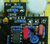
This one? It's part of the polarity protection, we don't use the BSP250 either.

It's not in the signal path so won't affect the tone.


1622675344697.png


Want to see something else interesting? (Maybe)

If you have a DMM check for continuity between the anode of the other zener diode (bottom left-hand corner of the board) and ground. On the original I had the ground plane was obstructed by another component so the diode wasn't actually making a connection to ground (thus floating / useless).

I'm curious to know if that was ever fixed.
 
Last edited by a moderator:
  • Wow
Reactions: fig
This one? It's part of the polarity protection, we don't use the BSP250 either.

It's not in the signal path so won't affect the tone.


View attachment 12330


Want to see something else interesting? (Maybe)

If you have a DMM check for continuity between the anode of the other zener diode (bottom left-hand corner of the board) and ground. On the original I had the ground plane was obstructed by another component so the diode wasn't actually making a connection to ground (thus floating / useless).

I'm curious to know if that was ever fixed.
I checked mine, ser.nr: gun0897 and the "SHO" zener does make a ground connection.
It's a "V1" big enclosure but the pcb states "V2.1" so that leads me to believe there are some previous revisions done.
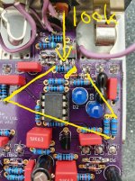
I tried to trace the "missing" zener and found it to be in a loop with the 100R resistor coming from the tone pot, as well as 2x 10k / a 100k and was curious to know if it did anything soundwise.
Thnx for your answer!
 
Note: I modified mine slightly with a 3.3k upon 4.7k for a bit more gain/ a 150nf and 220nf metal film cap instead of the tantalum and a silver mica 47pf instead of the original 51pf ceramic.
The 100k in my pic was original though.
I drew the trace of the zener too.

20210603_090030.jpg
 
Last edited:
It's 100K in this one as well.

1622705147791.png

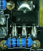
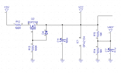
Are you sure about the connection from the cathode of the zener to the top end of the two 10K resistors? It should be connected to the bottom end of the one on the right. It's harder to see in my pic but in yours you can see the ground plane thermals on those two connections.

(Technically it's the VCC plane, the ground plane is on the bottom side)


My RefDes won't match anything printed on the board (and my symbol for Q2 isn't correct), but this is what you should have:
1622705621983.png
 
Back
Top