
Help. So I had built the six string singer going to get an S RV sound. I even have a video putting all the pieces and the board and soldering them. I still need to edit, I will be putting up on YouTube and completed. When I completed all the soldering I had really thought this thing was going to function well though I was missing some of the required components as in parts of course I wanted to try and see if I can get a little sound out of it so I soldered the wrong value pads expecting to change them out later. When I connected the pedal I was getting a lot of static but no clear sound(I assume this had to do with the wrong value parts) I proceeded to take them out and complete the wiring and now the pedal does not work at all I need help.
You are using an out of date browser. It may not display this or other websites correctly.
You should upgrade or use an alternative browser.
You should upgrade or use an alternative browser.
Six Sting Singer: COVID-19 Pedal Relief
- Thread starter l_elu
- Start date


That’s not really a lot of info to give trouble-shooting on. But here’s a few thoughts.
1. Some of your solder joints looks big and kinda messy, may be an indication that some joints are cold.
2. lots of damage on pot pads from desoldering, it might not work when you reinstall them.
3. do you know how to use a multi-meter and audio probe? These tools allow you to find if it’s a power or signal issue, and where the problem is occurring
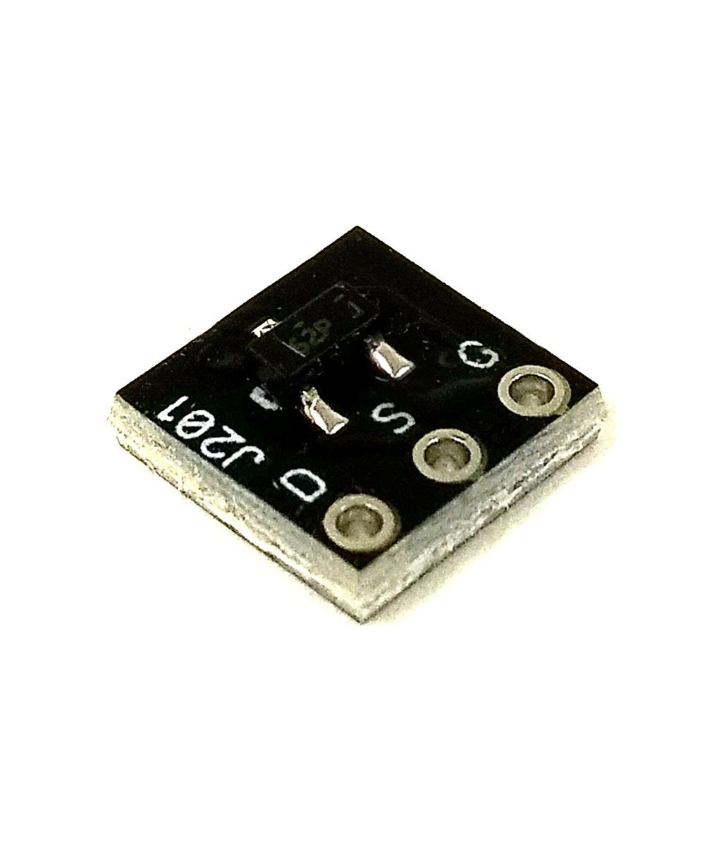
4. Where did you get your Jfets? There are many fakes out there since it’s a discontinued product (I recommend using the smd adapter board)
5. We can’t see your offboard wiring to see if there’s a problem there.
6. I don’t understand your comment about ground reading, not all those connect to ground.
since the board has a lot of damage, I’d recommend starting over, use the right components, take your time to get good solder joints. Read the Basic Workflow Tips post pinned to the general questions forum.
1. Some of your solder joints looks big and kinda messy, may be an indication that some joints are cold.
2. lots of damage on pot pads from desoldering, it might not work when you reinstall them.
3. do you know how to use a multi-meter and audio probe? These tools allow you to find if it’s a power or signal issue, and where the problem is occurring
4. Where did you get your Jfets? There are many fakes out there since it’s a discontinued product (I recommend using the smd adapter board)
5. We can’t see your offboard wiring to see if there’s a problem there.
6. I don’t understand your comment about ground reading, not all those connect to ground.
since the board has a lot of damage, I’d recommend starting over, use the right components, take your time to get good solder joints. Read the Basic Workflow Tips post pinned to the general questions forum.
not sure what you mean about trying to use the wrong parts. do you mean you were substituting values of the right kind of part that were just a little different?
as noted, looks like you may also have damaged your board from adding and removing parts. and if you were wiring your pots in to the board while waiting for the right pots that would fit in those holes, you may have problems in those connections but it is hard to tell because the board is slightly out of focus, and because you have not posted pictures showing whatever off-board connections you have.
at the very least I suggest avoiding any part substitution unless it is a very minor difference in the value of a resistor or a capacitor. and if you don't know what a very minor difference might be in the values for those parts, post a question on the forum.
it is also way too easy to accidentally put in the wrong value of a resistor in a circuit even when you think you are putting in the right part, making a circuit not work well, or not work at all. you need to learn how to double check the values of the resistors both before you solder them into the board and when something goes wrong and you are trying to diagnose a problem.
take time to carefully read through the workflow tips in these forums, and spend some time looking for youtube videos that will teach you how to use your digital multimeter. learn how to build and use an audio probe -- it only uses a few parts you may already have at hand, and it will give you instant information about what is or is not working in different parts of the circuit board.
as suggested, it might be easier to start over when you have a new board and all of the right parts if you want to keep it simple. but you can put in some time to learn some of the basic info you need and try to get this board working instead, or use it to learn more while you are either waiting for new parts to arrive.
Thank you all who have responded. I will shortly be putting all the measuring that I got in DC voltage across the board resistors included.
Ha That’s exactly what happened it calls for a 500K pot and I rest the gun and put in a 10 K pot. It’s strange because I was building another paddle at the same time as this one, and the other one works perfectly. I made an audio probe but I’m still not getting any sound. I checked the conductivity and everything seem to be connected properly. I am still runninginto trouble. I just don’t like giving up on my DIY projects, got to keep that Kobe mentality alive!!! I feel that this would just be the ultimate troubleshooting project! I have already learned a lot due to this problem. So don’t worry I won’t take it as cold as cold as you want as long as we can get this solved.
Ha That’s exactly what happened it calls for a 500K pot and I rest the gun and put in a 10 K pot. It’s strange because I was building another paddle at the same time as this one, and the other one works perfectly. I made an audio probe but I’m still not getting any sound. I checked the conductivity and everything seem to be connected properly. I am still runninginto trouble. I just don’t like giving up on my DIY projects, got to keep that Kobe mentality alive!!! I feel that this would just be the ultimate troubleshooting project! I have already learned a lot due to this problem. So don’t worry I won’t take it as cold as cold as you want as long as we can get this solved.
Also I got my Jfets from mouser! It does seem to me that those readings are a little strange but this is my first time dealing with them. Now you might be able to make the connection between why I think there is a problem on that side of the schematic and in my board.
| R1 | - | - |
| R2 | 6.84 | 6.81 |
| R3 | 9.02 | 4.48 |
| R4 | - | 4.48 |
| R5 | 2.24 | 4.48 |
| R6 | - | - |
| R7 | - | - |
| R8 | .31 | - |
| R9 | - | - |
| R10 | 9.02 | 4.48 |
| R11 | - | 4.48 |
| R12 | - | - |
| R13 | 2.24 | 4.49 |
| R14 | - | |
| R15 | -/.01 | .03 |
| R16 | - | - |
| R17 | - | - |
| C1 | 4.48 | - |
| C2 | 9.02 | - |
| C3 | - | - |
| C4 | 9.02 | - |
| C5 | 5.02 | 2.24 |
| C6 | 5.02 | .01 |
| C7 | 4.48 | - |
| C8 | - | .02 |
| C9 | 2.24 | 5.06 |
| C10 | 4.87 | - |
| C12 | - | -/.01 |
| D1 | 9.22 | 9.02 |
| D.C. | 9.22 | |
| L.E.D | 9.22 |
| Q1 | 9.02 | 5.02 | 2.24 |
| Q2 | 5.02 | .31 | - |
| Q3 | 9.0 | 4.67 | 2.24 |
| Q4 | 4.67 | 1.72 | - |
Also I got my Jfets from mouser! It does seem to me that those readings are a little strange but this is my first time dealing with them. Now you might be able to make the connection between why I think there is a problem on that side of the schematic and in my board.
R1 - - R2 6.84 6.81 R3 9.02 4.48 R4 - 4.48 R5 2.24 4.48 R6 - - R7 - - R8 .31 - R9 - - R10 9.02 4.48 R11 - 4.48 R12 - - R13 2.24 4.49 R14 - R15 -/.01 .03 R16 - - R17 - -
C1 4.48 - C2 9.02 - C3 - - C4 9.02 - C5 5.02 2.24 C6 5.02 .01 C7 4.48 - C8 - .02 C9 2.24 5.06 C10 4.87 - C12 - -/.01 D1 9.22 9.02 D.C. 9.22 L.E.D 9.22
Q1 9.02 5.02 2.24 Q2 5.02 .31 - Q3 9.0 4.67 2.24 Q4 4.67 1.72 -
- = no reading
-/.01= it would give me a reading of .01 Occasionally but that could have been the bad angles I have testing it
GenoBluzGtr
Active member
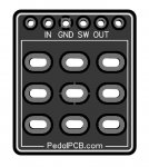
The holes in the FS Breakout board are somewhat self-explanatory. The Board gets soldered to the switch. MAKE SURE YOU SOLDER IT... just because it seems to fit tightly to the FS lugs, doesn't mean you've got a connection to every lug!. The labeled holes should be easy to figure out - IN GND SW OUT all go to the same labels on the PCB... "GND" may go to "-" and SW may go to "+" but should be simple. The two outer holes on either end will go to the "hot" input lead (the tip lug) on the audio jacks. The left-most non-labeled hole goes to the Input jack the right-most non-labeled hole goes to the output jack. Make sure you install the Breakout board with the labels (in gnd sw out) facing you, the other side is against the switch.
also, if your PCB has four holds and only the two innermost are labeled "GND and SW"... the adjacent unlabeled holes go to the "IN" and "OUT" on the switch breakout board. should be all in a row with no crossing over.
If you're using the enclosed jacks, the "Common" or "sleeve" lug is the one that comes from the part of the jack that is angled. I think of this as a ground, but it's really just a common that gets wired to a grounded pad on the PCB. The Tip is the other lug opposite that one - that this gets the input from the switch.
Hey first and foremost thanks for the response I thought this post had gone cold. Also thank you for the clarification on the break out board connection with the jacks. Not to toot my horn but it seems like all that wiring seems correct. II just wanted to second opinion on the break up or connections and was hoping that would be the problem but not
Still willing to help, just not sure what your status is. Did you get all the right parts and reinstall the pots? When you reinstall the pots, check for continuity with the multimeter with the components that should attach to each lug, since it looked like some of your solder pads were damaged.
Yes every part that the pedal cost for I have properly “I hope” installed. There is continuity amongst the parts. For some reason I still have a feeling the breakout board may have something to do with my issue of no sound. Do you suggest any ways of testing the breakout board. Are there certain logs on the breakout board that would have continuity as well. I have a video installing the parts it pretty long but I can upload it if it help. I really wanna find the problems through testing though. A lot of the numbers look off so I have a feeling that’s were the problem lies
try cleaning your PCB with isopropyl alcohol (IPA) if you have some. see if you can get a sharper focus on the PCB surface after it is cleaned, also try to have some photos that show the board where the wires are now in the way of looking at the connections.
look carefully for places where you may have stray bits of wires shorting to something beside them (parts or other wires). those are some of the places where you may have the most likely issues with faulty connections.
look carefully for places where you may have stray bits of wires shorting to something beside them (parts or other wires). those are some of the places where you may have the most likely issues with faulty connections.