SOLVED: Brown Betty Issue. No sound.

Loxton

Member
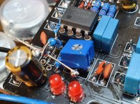
Hi, I'm having an issue with no audio when engaged.
The volume pot and trim pot has a scratchy audio when turned.
Led4 lights up when the trim pot is fully counter-clockwise.
Led3 lights up when turned 1/4 turn - fully clockwise.
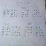
I have audio up to IC2 pin 2 and 7 then nothing after that.
R14 was removed and retested great but no audio on the left side of it. No audio at C9.
Replaced IC2 with same results.
I replaced the trim pot with the same results

I'll re clean the board and get some more info and pictures.

See IC readings in attachment 20220518_194855.jpg 20220518_200433.jpg
 
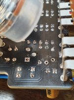
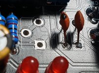
That looks like a board layout error. Square pads should have a square clearance area around the pad. Oops.
I had already removed the trim pot, R14 and C9, inspected and replaced them before I started asking for help. I'll remove them again, do some digging and report back later. Thanks a bunch for all your help.
The only way you're going to fix this board is with a knife. You have to cut away the ground plane around the corners of the square pad on both sides. PedalPCB quality is normally excellent, but now and then shit happens. I'm sure Robert will make it right.
 
I had already removed the trim pot, R14 and C9, inspected and replaced them before I started asking for help. I'll remove them again, do some digging and report back later. Thanks a bunch for all your help.
Once you remove them, Check for continuity on the individual Pads & GND on the problem areas!
 
That looks like a board layout error. Square pads should have a square clearance area around the pad. Oops.

The only way you're going to fix this board is with a knife. You have to cut away the ground plane around the corners of the square pad on both sides. PedalPCB quality is normally excellent, but now and then shit happens. I'm sure Robert will make it right.
It can be fix by drilling Trim 1 Pad larger & running a separate Jumper from Trimmer 1 Leg to C9/R14 ???? if that is the Issue
 
You have to cut away the ground plane around the corners of the square pad on both sides.
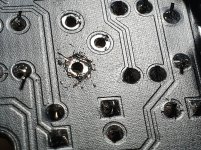
Solved. I carefully cut away the ground on all 4 corners on both sides, careful not to cut the trace to R14/C9. Had to check a few times with a multimeter. Then I made sure I didn't add to much solder, where it would flow into the ground section.
Thanks all for your help. 20220519_121733.jpg 20220519_122628.jpg
 
That is very unusual, I'll pull some boards today and see if more have this same issue.

The solder mask/ground pour clearance is designed into the component footprint so I'm puzzled how such a thing could have happened unless it's a fabrication error (also not very common).

The layout hasn't been changed in years, when did you order that PCB?
Nevermind, I see it hasn't been that long at all.

Let me look into this today and see what's going on. I should still have this same batch.
 
Back
Top