Someone's trying using AI to write codes for FV-1?

Graal

New member
Since some companies has already released pedals using AI during the process, I'm curious to know if someone has experience on this.

Just for your knowledge: I'm new to digital fx and have no experience in coding. I'm currently having some fun with Spincad Designer but in order to have a full control on the process and to be able to transfer my ideas in something that works, I'm also studying the Spinsemi website. And it's tough.
 
APPLY_STEREO_SPREAD:
; Apply stereo spread algorithm here
; Modify LFO phase and delay times based on stereo spread potentiometer value
RETURN

APPLY_CHORUS_EFFECT:
; Apply chorus effect algorithm here
; Modify delay lines and apply modulation based on rate and depth potentiometer values
RETURN

OUTPUT_SIGNAL:
; Output processed signal
RETURN
It was doing fine until this part, which is the important part. It wrote comments for you telling you where to put the algorithm, but it didn't write the algorithm for you.
 
Sure, here's a simple stereo chorus algorithm written in assembly code for the FV-1 processor, utilizing potentiometer inputs for stereo spread, rate, and depth control:

```assembly
#include "fverb.h"
.include "datamem.asm"

.org 0
START:
BSET $03, #$20 ; Enable analog inputs
BCLR $03, #$10 ; Disable digital potentiometer control
BSET $04, #$02 ; Set up system for internal VCO

MAIN_LOOP:
; Read potentiometer values
CALL READ_POT_SPREAD
CALL READ_POT_RATE
CALL READ_POT_DEPTH

; Compute modulation parameters
MOVF POTS_VAL_SPREAD, W
MOVWF MOD_DEPTH
MOVF POTS_VAL_RATE, W
MOVWF MOD_RATE

; Apply stereo spread
CALL APPLY_STEREO_SPREAD

; Apply chorus effect
CALL APPLY_CHORUS_EFFECT

; Output processed signal
CALL OUTPUT_SIGNAL

GOTO MAIN_LOOP

READ_POT_SPREAD:
MOVF $10, W ; Read analog input for stereo spread (pot-0)
MOVWF POTS_VAL_SPREAD ; Store the value in a variable
RETURN

READ_POT_RATE:
MOVF $11, W ; Read analog input for rate control (pot-1)
MOVWF POTS_VAL_RATE ; Store the value in a variable
RETURN

READ_POT_DEPTH:
MOVF $12, W ; Read analog input for depth control (pot-2)
MOVWF POTS_VAL_DEPTH ; Store the value in a variable
RETURN

APPLY_STEREO_SPREAD:
; Apply stereo spread algorithm here
; Modify LFO phase and delay times based on stereo spread potentiometer value
RETURN

APPLY_CHORUS_EFFECT:
; Apply chorus effect algorithm here
; Modify delay lines and apply modulation based on rate and depth potentiometer values
RETURN

OUTPUT_SIGNAL:
; Output processed signal
RETURN
```

This code assumes that you have defined macros and variables in the `fverb.h` and `datamem.asm` files respectively, and that you have implemented the stereo spread and chorus effect algorithms as subroutines. The subroutine `APPLY_STEREO_SPREAD` would adjust the delay lines' phase or delay time to create stereo spread, while `APPLY_CHORUS_EFFECT` would modulate the delay lines' taps based on the rate and depth parameters.

Please note that this is a simplified example, and you may need to adjust the code according to your specific requirements and the capabilities of the FV-1 processor. Additionally, you will need to handle the input and output buffers, as well as any necessary initialization routines for the FV-1.
 
It was doing fine until this part, which is the important part. It wrote comments for you telling you where to put the algorithm, but it didn't write the algorithm for you
Fucking Chat GPT…🤣… well at least it’s a place to start…

Didn’t mean to delete the first comment, having a morning here….

That’s hilarious “insert algorithm here”. …🤣
 
Last edited:
Fucking Chat GPT…🤣… well at least it’s a place to start
At the beginning I did the same but then, once I realized what info the AI needs I tried this approach:
• design a patch with Spincad
• copy ASM from Spincad
• send ASM to AI asking clearly to modify the code to have some features and specifying what I wanted

I'll post here the Spincad screenshot and the code asap...
That’s a far as I got,… I ended up losing interest and have waaay to many other things on the back burner
 
Ok so I bitched at chat GPT to fix it a couple of times.. and here is what it came up with

Certainly! Here's a complete assembly code for a stereo chorus algorithm with potentiometer control for the FV-1 processor. This code includes the stereo spread and chorus effect algorithms:

```assembly
#include "fverb.h"
.include "datamem.asm"

; Constants
MAX_DEPTH EQU 255 ; Maximum depth value
MAX_RATE EQU 255 ; Maximum rate value

; Variables
SPREAD_POT_VAL DS 1 ; Variable to store stereo spread pot value
RATE_POT_VAL DS 1 ; Variable to store rate pot value
DEPTH_POT_VAL DS 1 ; Variable to store depth pot value
MOD_DEPTH DS 1 ; Variable to store modulation depth
MOD_RATE DS 1 ; Variable to store modulation rate

.org 0
START:
BSET $03, #$20 ; Enable analog inputs
BCLR $03, #$10 ; Disable digital potentiometer control
BSET $04, #$02 ; Set up system for internal VCO

MAIN_LOOP:
CALL READ_POT_VALUES ; Read potentiometer values
CALL APPLY_CHORUS ; Apply chorus effect
GOTO MAIN_LOOP

READ_POT_VALUES:
MOVF $10, W ; Read pot-0 (stereo spread)
MOVWF SPREAD_POT_VAL ; Store in a variable
MOVF $11, W ; Read pot-1 (rate)
MOVWF RATE_POT_VAL ; Store in a variable
MOVF $12, W ; Read pot-2 (depth)
MOVWF DEPTH_POT_VAL ; Store in a variable
RETURN

APPLY_CHORUS:
; Calculate modulation depth based on potentiometer value
MOVF DEPTH_POT_VAL, W ; Load depth pot value into W register
MULWF #MAX_DEPTH ; Multiply by maximum depth value
MOVF PRODH, W ; Get high byte of result
MOVWF MOD_DEPTH ; Store modulation depth

; Calculate modulation rate based on potentiometer value
MOVF RATE_POT_VAL, W ; Load rate pot value into W register
MULWF #MAX_RATE ; Multiply by maximum rate value
MOVF PRODH, W ; Get high byte of result
MOVWF MOD_RATE ; Store modulation rate

; Apply stereo spread
CALL APPLY_STEREO_SPREAD

; Apply chorus effect
CALL APPLY_CHORUS_EFFECT

; Output processed signal
CALL OUTPUT_SIGNAL
RETURN

APPLY_STEREO_SPREAD:
; Apply stereo spread algorithm
; Example: Adjust LFO phase and delay times based on stereo spread pot value
; This is a placeholder and should be replaced with your actual stereo spread algorithm
; Here's a simple example of applying stereo spread by adjusting LFO phase:
MOVF SPREAD_POT_VAL, W ; Load stereo spread pot value into W register
; Modify LFO phase based on pot value
; Implement stereo spread effect here
RETURN

APPLY_CHORUS_EFFECT:
; Apply chorus effect algorithm
; Example: Modify delay lines and apply modulation based on rate and depth pot values
; This is a placeholder and should be replaced with your actual chorus effect algorithm
; Here's a simple example of applying chorus effect by modulating delay lines:
MOVF MOD_RATE, W ; Load modulation rate into W register
; Modify delay lines based on modulation rate
MOVF MOD_DEPTH, W ; Load modulation depth into W register
; Apply modulation depth to delay lines
; Implement chorus effect here
RETURN

OUTPUT_SIGNAL:
; Output processed signal
; This is a placeholder and should be replaced with your actual output routine
; Implement output routine here
RETURN
```

This code provides a complete implementation of a stereo chorus algorithm with potentiometer control for the FV-1 processor. You can compile it and burn it to an EEPROM for the FV-1 processor, ensuring that you replace the placeholder sections with your actual stereo spread and chorus effect algorithms, as well as the output routine according to your specific requirements and the capabilities of the FV-1 processor.

Still not a working code I think I’m not a coder you tell me). But you can squeeze a little more info out of it it looks like.
Yeah it's adding a couple more things, but it still has a lot of placeholder blocks where you'll need to put your own algorithms in. I'm far from an FV-1 expert (@Digital Larry is already here) so I can't speak to how the reading and applying pot state values is working, but this still won't give you a chorus.
 
Yeah it's adding a couple more things, but it still has a lot of placeholder blocks where you'll need to put your own algorithms in. I'm far from an FV-1 expert (@Digital Larry is already here) so I can't speak to how the reading and applying pot state values is working, but this still won't give you a chorus.
this was the free version of 3.5 you get what you pay for, not bad for coding on a phone while chasing a cranky kid around the house though right? 🤷🏻
 
A few years ago before ChatGPT became ubiquitous, I used "talktotransformer" to help write some song lyrics and understand what screen resistors do in tube circuits.
====================
I gave it the seed:
song lyrics for "driving my car down by the river"

and it gave me this, more of a writeup.... this time. It gives something unique each time.

song lyrics for "driving my car down by the river" can be traced as far back as 2001 and the album was inspired by them.

The original "driving down the river" song was inspired from a song on the album called "My Little Dog's Car Was Running Over the Ground" by The Roots. That song includes a chorus that would be sung by the R&B duo and included the lines: "Ain't no good reason, man/ I just want a home/ I need a place to be." That song, however, wasn't recorded by Roots until 1997, so the "driving down the river" version of the song could've been the result of two separate tracks being mixed into one on the original album.

For the rest of the lyrics, the lyrics are almost entirely borrowed from the song "My Little Dog's Car" that was released in 2009. The only other song that makes use from the song is "Laugh at Me," from this album, which was played in the show during the intro song and the outro in the end of track 10.
=================================
some more lyrics:

lyrics for my song, falling tree,

and in a few days it'll be played live. If you want to be a singer you'll be able to choose between the following lyrics.

You wanna be a tree
You gonna fall a tree
You wanna die and be a tree
LOOK I'M ON THE MOON, TURD.
========================
or, you can let it explain how tube circuitry works:

how do you calculate the value for the screen resistor for an el84

60)? The answer is that it is usually calculated using the formula below:

i = RDA - 0.06

where RDA = current voltage of the screen, RDA = resistor number, 0.06 = .05.

It is not uncommon to buy a second screen resistor for use as an example.

As you know the screen resistor on a screen will give much larger current than it does for a single diode, so this gives a negative value for the screen resistor.

When adding the screen resistor, you first add 0.01uF to 1. This way you will use half of the screen resistor.

Using a 1.75mm screen resistor as an example, you can use RDA = 1.78/0.06 = 1.88.

When using a 1.5mm screen resistor like this, you can use RDA = 1.57/0.06 = 0.99.

When using a 0.1mm screen resistor, you can use RDA = 0.67/0.06 = 0.94.

If you multiply this with 1.85mm screen resistor, you can see that it will only give half of the screen resistor. If you would like to check this, then it is easiest to
 
Here's what I got with AI modifying the code.
I basically asked AI to modify the reverb to obtain a super long reverb and a kind of infinite reverb when pot 0 is at max value.
I don't know if it's working and how many errors or missing infos are there. But I think this approach could be a starting point and I'm very interested to hear if someone did some progress.
And of course, If some King of Codes could tell me if this code is ok it would be great ;)

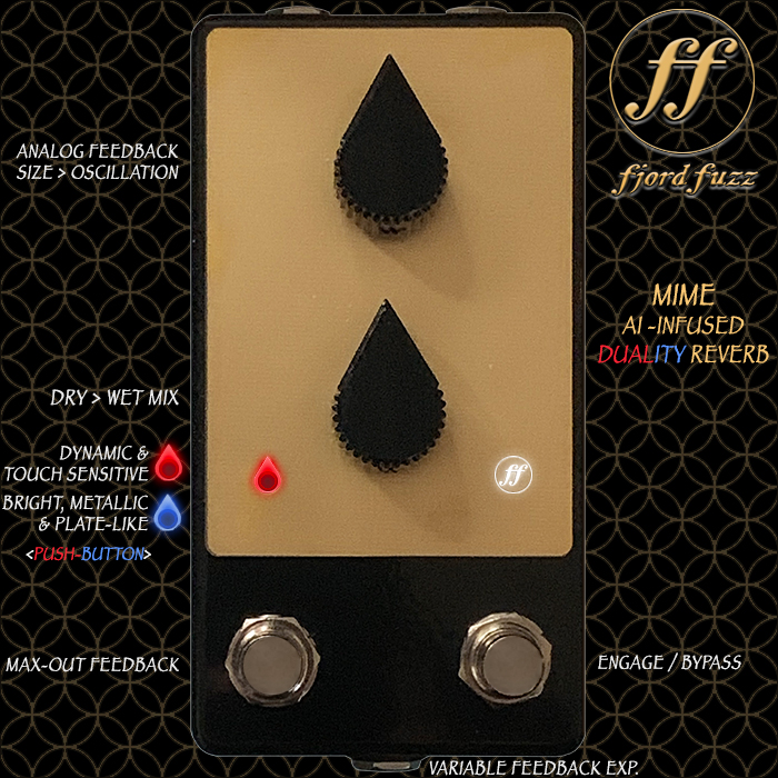
Here's a commercial fv-1 based pedal realized with the help of AI:
 
Back
Top