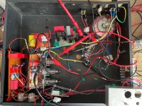
Stuffed Crust (176 inspired tube class A compressor)

NickKUK

Member
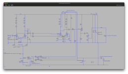
This is a real time build log.. so you're gonna get some LTspice first ... (mods if this isn't acceptable for the competition, let me know)

I have a compressor. It's small, petite, is a Ross-style one which is.. ok.. but it's not great.

My journey started with thinking - that Cali76 stacked compressor sounds good. The Cali76 is based on the 1176 which is a FET based solid state compressor. It's fast and clean, the gain is controlled by a FET acting like voltage divider with a pre amp, a post amp and a 'gain control' which really just decides if the output is too loud and adjusts the FET to reduce the signal (it's like varying the voltage divider). The 1176 is a current based low voltage design and uses an opamp to perform the comparison to adjust the FET.
The Cali seems to be a stack of these allowing a soft stack and a heavier second stack to be setup with different aggression and release.

However the 1176 is really the continuation of a saga.. before that sits the fabled 176 compressor which is all tubes.

The 176 uses a very similar mechanism to the 1176 in terms of its building blocks but the details differ heavily. The 176 doesn't use a FET voltage divider but instead varies the grid bias of the first amplification stage. This essentially changes the volume and creates a "variable gain" (I use quotes because the tube gain itself doesn't change).
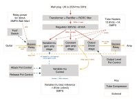
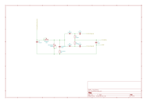
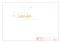
The 176, when stripped down to bare bones, is basically a variable volume amplifier stage, a gain stage that creates the output waveform that is output and the gain control that uses a glass diode tube to rectify that signal so we know how big it is, then uses that to vary the volume of the first stage. A louder output wave form = a higher peak, which in turn reduces the volume by decreasing the input amp's grid voltage, making it more negative and reducing the signal out of the tube.
I said negative - but there's no negative power I hear! - correct. The output wave rectification is done to drive the diode's output negative (in the same way as creating a negative bias voltage ref in a tube amp). The result is we get the 'loudest' sound as a negative drop.. which when applied to the bias of the grid causes the entire thing to lower its operating point. Trippy!

Here's an example of the output dropping the bias voltage:
Screenshot 2025-07-17 at 11.05.46.png

Another example with a number of quiet and loud transitions that are brutally abrupt - this is possibly the worst case scenario:
Screenshot 2025-07-17 at 11.06.50.png
Time 0 to 4 seconds is a very small 10mVpk signal - that leaves the tube amplifying (the tube is biased at 12V, so 12-12.5 = -0.5Vgrid.. which is like turning up to 10 on the dial)
Time 4-16 seconds is a 1Vpk signal that causes the system to adapt to reduce both immediately (with a little overshoot) and in a longer slope. This is still ok and so it turns the dial down a little ... a bit like turning the volume dial down to 8..
Time 16 seconds gets a 3.16Vpk for a few cycles.. the volume dial gets turned way down.. 8.20-12 = -3.8Vgrid .. so that's like turning it down to 3 on the volume dial.

So the frequency response doesn't seem too bad at any input level and frequency:
Screenshot 2025-07-17 at 11.20.22.png
Screenshot 2025-07-17 at 11.22.31.png

So the original version of the 176 has some inter-stage transformers and an output transformer.. which are kind of expensive .. each. So my version of this classic old design has a few mods:
1. I dropped the iron. So there's no interstage transformer or output stage push pull.
2. I'm using 12BH7A-STRs which are linear sounding triodes and can driver up to 20mA, operating point for bet sound is 12mA.
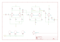
3. I dropped a gain stage.. so I now simply have two stages compared to the 176's three. It still works fine. The important point here is that the last gain stage creates enough voltage swing to drive the gain control and thus control the gain of the first stage.
4. I dropped the tube diodes for humble UF4007s.
5. I added a ecc99 cathode follower line driver. The ecc99 is a brute with 60mA max and a best sounding operating point at 24mA! This cathode follower stage was added to prevent any output line issue later reflecting on the gain control. It means the 12BH7A can drive the gain control and leave the ecc99 driving the line.
6. I use a voltage divider on the output to prevent the system from frying any electronics.

And there you have it.. Stuffed Crust Compressor, it's a very upper-crust and over-engineered solution and a 'pedal' stuffed with tubes and transformers..

A couple of final points.

First - Sound - the tube 176 with push-pull transformer is slower and warmer sounding, the solid state 1176 is faster with more detail due to the opamp+FET control. My version has no push-pull so it's going to sound class A sweet without a transformer cancelling harmonics. There's nothing stopping an opamp replacing the gain control section, or putting a FET+resistor in which would then create a hybrid that has sweet class A sound but then the speed of the FET+opamp creating clarity.

Secondly - danger danger high voltage! - this running a B+ of 330Vdc. I tried doing a 24Vdc B+ but it all becomes very sensitive to minute changes with the real small grid biasing. Tubes like voltage.

Finally, Noise reduction - this has a basic RC filtering, but it's also possible to use a voltage regulator.

I still have some work todo.. before getting the soldering iron out, but this design looks feasible.
 
So the plan this weekend is simple:

Stage 1 - check the variable volume works.
1. Make power supply by rip out the HV and heater power supplies from the old tube headphone amp.
2. Cut a wood board out for mounting hardware (I'll switch to alu once I know this step works)
I'll basically use the bench supply for the bias, signal generator for the input and scope for the output. This should give a decent test to see if this will fly.

Stage 2 - build gain and output CF stage with basic waveform range selection (ie using a clip rather than a switch)
This should be relatively straight forward and will give the signal for the control stage.

Stage 3 - make the control circuit
This should be relatively straightforward.. but getting it dialled in will be the fun part.
I'll look at making a bypass switch/relay switch, I think at the moment I won't make a dry+wet mixer.

Stage 4 - if it's all a bit noisy
I have a couple of things I have recovered/lying around:
* a pair of speaker metal shields that may fit the toroidal transformers (they look like they will) but I think these may be ok in alu
* if the rectifiers are noisy (I'm expecting they will be) then the all enclosure can be 'adjusted' to make some shielding.
* if the HV power is noisy then I have a maida regulator that should handle 300V (it runs a MOSFET in front of a LT3080)
* if there's still mains noise then I can replace the IEC connector by stealing the Schaffner IEC filter on my old amp. The one from the headphone amp got recycled into my guitar amp.
* I have some ferrite around that could work if there's high frequency noise causing a problem with the gain bias. I can make a LPF on that if need be.

At this point it will be about as safe as ... politics ;) but I should have it all working on the test equipment.

Stage 4 - fab the al-u-min-i-um (not alooominium) pedal out of sheet aluminium I have lying around. This will need annealing and it's meant to be thunderstorms and rain..


*robotic voice* Recycling.. Recycling..
IMG_4767.jpg
 
Last edited:
Been working through the resistances needed.. one is a 12K 8W cathode resistor for the output ec99 driver. Nope. So an option here is to use one of my DC SOA capable 950V MOSFETs.. Then run 3.5-4V on the gate and let the heatsink take the load. I think that will work.

I think I won't have enough resistor to make power dividers required but I do have a variable low noise 3 channel supply I built for my ADC. That I can power from a bench supply and tune. The entire lot can be ground ref'd to the tube ground. This solves a number of problems and removes the need for the resistor dividers 🥳

The hacks continue..

EDIT:
So I think I have everything.. with some fudging...

The only thing I don't have is an output jack.. but when all fails - direct soldering...
 
Last edited:
It occurred to me last night, an option here issue the second ecc99 triode. I know TubeCad loves doing this for his headphone amps, but in this instance it works nicely. I may add a grid blocker to prevent RF interference on the output creating noise.
Screenshot 2025-07-21 at 07.36.53.png

This option provides a little more mA swing and means I don't need the mosfet or the DC for the grid. It's also a little push-pull which helps but remains firmly in the class A operation. There would be some cancellation (as you're running NFB into the grid of the lower ecc99) however if you want some subtle overdrive tone then you can increase the size of C11 here - it seems to create a more lopsided waveform.
 
Last edited:
Just a starting test to ensure this board works. The signal I'm using here is between 1 to 20V peak-to-peak, however in the compressor it will be subject up to 80V peak-to-peak


You have to remember the tubes are cathode biased at 15V, so the grid is operating at -15V then this bias is layered on the top. So a louder signal results in a drop in the voltage causing the -15V to drop to -20V etc which reduces the signal output (volume). It seems a bit counter intuitive but once you take into account the tube cathode it makes sense.

I now have two boards ready, they need a little tweaking but they're designed to have trim resistances to tune the tubes.

The sockets hardware is almost done too. After that it's test the power, this will see the 300+Vdc and then we'll see how the boards hold up, test the operational points of the tubes (the trims) and then get it on the bench with some signals going through.

Only after that I'll feel safe enough to plug a guitar in and an amp (tube amp) with the scope attached to record peak transient.

Only when I'm happy the peaks of any transients aren't going to destroy anything then I'll see how it works with the pedals.
 
Last edited:
Mmmmm....
IMG_4797.jpg

Currently setup on the bench supplies with a B+ of 61Vdc rather than 330-350Vdc. This allows me to test it and see it working whilst running on a current limiting power supply. I've then scaled the bias voltage down to 5V rather than 15V.


So when you watch this - the input signal (blue trace) gets pushed from 1Vpp to 20Vpp 82Hz (E1). The output signal (green trace) start to soft distort but never gets above 3.16Vpp. As the input is turned up you can see the yellow control board drop in voltage.

I'm missing a couple of things - the rate of release currently doesn't have it's full resistance (I forgot to solder in a meg resistor in series with the variable resistor).
 
Now running full B+ which means around 330Vdc B+ and 250Vdc on the plates.


I've made a few changes:
* running off mains and full voltages
* heaters now running AC to keep voltages up
* waveform is sampled from just above the plate but not directly at the moment. So it's more sensitive.
* control bias voltage dropped from 15V to 2V

In the video below 1V gets a little amplification, so 1Vpp=>1.15Vpp but the 2Vpp and above slowly drop in output voltage. 20Vpp input now results in a 11Vpp output for example.

I can tune the more but for now that will do.
 
If this works out I may put the design on a PCB or set - it should allow reduction of size and mess. I've designed and built two PCBs before - a 4 layer 24MHz clock board with low phase noise clock, 1:3 clock spanning IC and power filtering and shunt supply, a 4 layer 24MHz i2s isolator with power supply filtering and shunt. If I do make a PCB it would allow a combination of 350V layout through hole and low voltage layout with surface mount. From experience I'd not mount the tube sockets direct to the PCB to reduce heat conduction and increase the lifespan of the PCB.

Today's plan for time and some thinking time:

* tune for guitar sensitivity rather than 20Vpp. This involves some cathode bias adjustments, the grid bias resistors can be increased a touch and I can also replace the detecting diodes for a lower forward voltage drop (UF4007 is ~1.7V but a 1N4007 is ~1V) I can simulate this and it makes a difference, so rather than mess around attempting to emulate it, I'll switch out the diodes. If I could guarantee a maximum of 20V then I could have used a 1N5817 that has as forward voltage drop of 0.4-0.7V however the wave form is closer to 40V full swing.
I can move the waveform taps to the top the tubes, so the increases the waveform Vpp so it make the system more sensitive and faster to respond.

* centre tap the heaters now they're running straight off a 12Vac secondary. The DC rectification + RC filter makes the heaters quiet but drops the voltage down to 10Vdc which isn't healthy for the heaters. Option for now is to use the second power supply.

* once the tuning works, I can then target the attack and release resistances. These affect the charge and discharge currents from the 0.1uF cap, with the attack controlling how much current is allowed to the cap and the release is how fast the cap discharges. The effect is that charging is how fast the gain adapts to high signal strength, and the release is how fast the gain returns back.

* tune the cap used.
The use of a capacitor is one of the key differences between a 176 and 1176. The reason is the 0.1uF capacitor discharges in a curve providing a softer return slope. I'm using a vishay MKP 1839, so based on the tangent loss curve, it's ESR goes from 8R (61Hz) to 0.3R (1KHz), but the 220uF nichicon MUSE bipolar ESR would be 1.4R to 0.08R (although they only give 120Hz 0.12 angle). This is quite annoying as the 220uF gives a better response but the size of 220uF also causes a longer RC charge/discharge cycle that slows the response time. So it's not all roses - I do have some polarised low ESR organic electrolytic but if the wave form accidentally drives the cap negative then this is not good for it.
Additionally I can't simply decrease the attack and release resistances plus increase the capacitance because this is being driven from the plate of the BH7A second stage.
What does this high ESR at low frequency mean? It means that for low frequencies the compressor will be slower responding and that means a higher chance of strong bass notes 'flubbing out'. With a 1uF MKP4 in that position, it reduces the ESR at 62Hz to 1.5R which is better and should still be ok with the load on the 12BH7As. The original 176 used a 12ax7 so they had less current to play with.

This is where a solid state opamp solution wins. It can drive current with little loading on the BH7A plates. Additionally, by doing away with the 0.1uF cap, the opamp can be built into a better control system .. but at the cost of additional phase shift. This is what the solid state 1176 compressor does. So it will give a better bass response and a better response in general across the frequency range.

Just modelling those changes, specifically with the resistances for 62Hz with the higher ESRs works well to improve response, the effect is the resistances for the attack and release need to be lower (which suits my pots but I will solder a 2K in parallel with the 20K pot for now) to give more current for charging the 1uF. Tapping the waveform at the plate also increases the current available for this.


I'll also update my ltspice schematic.
 
Last edited:
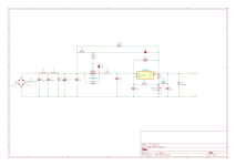
So I'm now down in the weeds (for tube amps) looking at the 10mV to 500mV range, and there's a good reason - my linear power supply is simple as it's a toroidal -> bridge rectifier -> RCRC (390uF each) -> B+. The B+ is reading 340.33Vdc but it has between 0.2-0.3V of ripple still according the brymen multimeter.

Here's the scope traces, yellow is output, ignore the green (probe not connected)
SDS00003.png

So I need something to get rid of the 0.2-0.3V (200-300mV) as it appears appears on the output which means there's 100Hz hum loud enough to be picked up by the amp running high gain.

Here's that yellow trace spectra - that's rectifier noise and lots and lots of harmonics.. 59dB...
SDS00005.png


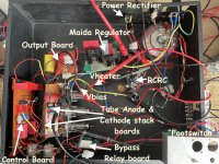
Back in the day it would require a large chunk of iron as a choke to remove that noise (like Marshall do). However I don't have that but I do have a lovely little board I made up previously - a maida regulator.

The Maida regulator is simple yet brilliant in its concept - it allows a low voltage regulator (LVR) to be used in a high voltage (way beyond the LVR limits). There's examples of this regulator running at over 300Vdc with LM317s, with 3080 and even 3042 LDO regulators! The 3042 can reduce your power ripple on 300+V to below 5uV. Yes microvolts.

The way it works is simple - a mosfet creates a small working window floating just below the 340Vdc input. With the floating window being about, say about 12V, the low voltage regulator only 'sees' the 12V with the ripple noise, so it cancels out the ripple noise on that 12V leaving you with a very clean high voltage output at the expense of loosing around 12V in this example of the output B+. In reality if you can reduce the ripple to a few volts, to fit within the window, then that window doesn't need to be that big. The 3080 drops out at 1V so there's the minimum drop but your noise may be more than that window can support.
The down side of a maida regulator is finding a mosfet with a DC Safe Operation Area (SOA) that supports continuous load at the high voltage on switch on (the mosfet sees the entire HV on startup). Most mosfets are now optimised for pulse operation for switching supplies and don't have the prerequisite DC SOA.

I just so happened to explore maida regulators with a LT3080 regulator at high voltage for a headphone amp. Here's the PSRR for the LT3080:

Screenshot 2025-07-25 at 10.47.31.png
As I'm pulling about 100mA only.. I'm looking at the upper line. So 85dB 100Hz noise rejection up to beyond the guitar range.. and 80dB well into the top limit of 20KHz. So about that 59dB... :devilish:

What we should see is that the noise disappears, although we will sacrifice some B+ to the regulator gods, so we may loose 2-5Vdc. Any lower and the 3080 may drop out (shut down).

Now comes the safety notice.. the STW mosfet and the LT3080 both have heatsinks attached.. but the rear of the devices is attached to the out pin.. which makes the heatsinks sit at 340Vdc.. (even with insulators the screw threads, or even plastic screws, the metal pieces are within the safety tolerance for spark over for these voltages. So you treat as if they're ⚡⚡monoliths of 340Vdc doom⚡⚡...
I have one that's really hacked together on matrix board, and it scares me as the heat sink are on both sides to keep the two devices as close as possible. At least the 3080 is running a full positive guard on the set pin 😁

IMG_4852.jpg

I may be tempted to remake the board using some turret board. Although a final option is to make my own PCB (I have some UV sensitive board and developer but it's a fuss) and if I'm doing that then I may as well make one for the entire compressor. The UV PCB is double sided too... and is still inside the competition rules as it's crap I have lying around.

The good news is that it will solve the noise problem.. with the remaining noisefloor being the tubes. Typically they're about -70dB to -80dB, and even with running differential amps to cancel some noise, it's not going to get much better.

I've worked out that I need to now ground the bias of the control board and it works really nicely at the lower input voltages, the grounding protects the 22uF from the negative voltages but if I want to have a configurable bias then using a small non-polarised cap 20uF (only needs to be 25V or 50V) will do fine. I can try one of my 220uF but there's a chance that it will take time to charge initially although it will have lower ESR at lower frequencies which would boost performance.

However this weekend is a break from the project.

EDIT: For now I think I will make the regulator a little more manageable - moving the second heat sink form the bottom side. It should have no real effect moving the mosfet a couple of mm away. It will make it less of a death trap and make it bench mountable.

I'm thinking that the PCB option would be good to have two boards to separate the noise:

* Signal board - this could be quite flexible and the THT components could then allow different tubes to be used - I've used low gain but there could be an option for 12ax7 for example but that would need R&D. I'd simply create the PCB with enough track spacing for 400Vdc and then it would be up to the person going off piste to make any changes.
Given the sizes of the small THT/SMD semiconductor components, it should be possible add options for opamp control and fet replacement for variable mu in the same footprint. Perhaps even switchable. There's considerable work needed to get through that though. The key here is it's still tube stages and to make a total move to solid state stages would result in replacing the power supplies too.
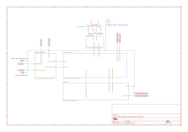
On the switchable - it could offer a low voltage cable for a foot switch (1/2") and then wire in bypass relay and perhaps a relay for mod.

* Power board - I'm thinking a combined board with fuses, regulators, filtering and rectification for both HV B+ to 400V and a LV DC Heaters. The board would connect to the secondary of an appropriate transformer.
I'd probably suggest using a small tube amp transformer, possibly even one of the very available fender guitar transformers. On the primary I'd leave it to the builder but I'd probably put a Shaffner IEC switch, fuse and line filter as they're cheap, professional and work.


Lastly .. for some light reading I came across this which shows the 1176 compression curves: https://eprints.hud.ac.uk/id/eprint...ET compressor in popular music production.pdf

Tubes have their own compression curves - so rolling the tubes (with appropriate changes) could be used to tailor the curves further.
 
Last edited:
Back
Top