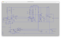
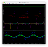
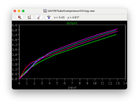
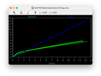
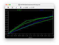
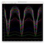
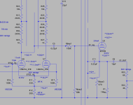
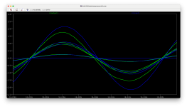
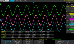
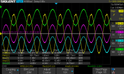
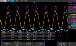
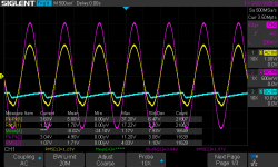
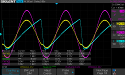
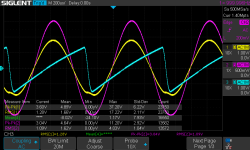
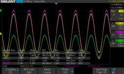
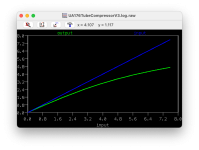
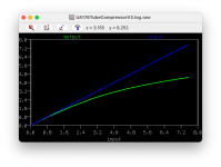
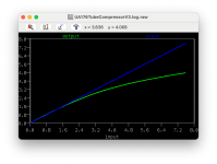
So we can break the tuning down to the constituent parts of the compressor:
1. The variable first stage - how the signal changes over changing bias and how do we tailor the stage accordingly.
2. The gain stage - this will be a constant gain, thus all we need todo is tailor to not distort and provide the signal size for the control
3a. The control peak threshold - how much energy is provided by the size of signal and the base grid point
3b. The control RC curve - how fast the attack and release responses are with that energy 'pump'. This will also affect the mapping between loudness of the signal and the attenuation - this will be the major non-linear component in terms of curve design. The cap also acts as a cathode bypass, so the value of the capacitance also affects the frequency response. f=1/(2pi*Rk*Ck).
4. The cathode follower - this is simply tuning it so it doesn't distort and drives.
So to point one - the "variable mu".
I'm not going to cover tube load lines - I would point you in the direction of Merlin "the valve wizard" as his site (although he sells a book on tube design) has on his site the free to download chapter on designing with tubes which includes the load lines.
The 12BH7A-STR is a low amplification but more linear equivalent tube to the 12AU7.
Drawing the load line:
* At zero current our Ra will have zero voltage drop and so our tube will see the 327Vdc B+.
* At a short circuit, the tube will see 20mA at 0V assuming a Ra of 327/0.020 = 16,350 ohms.
This 16K Ra sets the load line slope. The lower the resistance, the steeper the slope, and vice versa. One thing to note here is a point on sound - a higher voltage will give a better cleaner/fatter sound but worse overdrive, and a lower is the opposite. So more resistance = more voltage drop. Hence we see 100K in Marshalls.. as we're not attempting to add tonal colour or distortion, we're going to keep to the lower end of the spectrum.
However out 6k2 we have at the moment needs an increase - the line is too steep and so we get minimal output and high current.
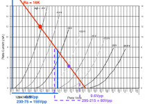
So here is our load line at 16K. 20mA is off the top.. we'll revisit this next post (AC line, following stage impedance and cathode lines) but it gives an approximate picture:

The normal operating point bias for the tube is set using the cathode resistor. This is set so the cathode sits at about +4.8Vdc. This means that when the grid bias is 0Vg that actually the tube sees the grid's bias as -4.8Vg. That's the red dot on the line. The curved lines are the grid voltages that the tube sees.
The operating point is the 0V point of the input sine wave - the +Vpk will move up the line towards 0Vg and the -Vpk will move down the line. I have demonstrated the points of a 4.8*2 = 9.6 Vpp signal would be and the output (blue lines and blue text) - so for a 9.6Vpp we get 155Vpp output.
The variable grid bias will shift the operating point down the line. So as the control board decreases the voltages, it pulls the operating point further down the loadline. I've put a purple dot showing the -13Vg (remember we have cathode +4.8V, so the control board only drops it by 8.2Vdc). The effect of the 9.6Vpp input signal peaks are now at -9Vg and -17.5Vg ... the purple dashed line and text show the non-linear compression... the 9.6Vpp now only outputs 80Vpp and not 155Vpp (a fully linear 1:1 would be 81Vpp). Dropping beyond -13V becomes increasingly non-linear and will start affecting the waveforms.
So our max attenuation will be 20*log10(80/155) = -5.745 dB of the loudest signal 9.6Vpp it will drop it to 4.95Vpp. I'm not going to play too much with dB simply because we end up needing to set a reference level if we're talking absolute.
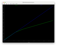
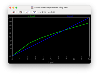
So you can see a minor curve I was talking about in my previous post appearing through the non-linearity of the tube. Changing the Ra and the tube to be a more non-linear tube such as the 12ax7, would see more of a bend. However we can also influence the curve in the control component - how fast the capacitor charges and how much it reduces.. but more on that in a later post.
So you can see I'm looking at the first stage:
* I've set a maximum input signal of 9.6Vpp - we could go smaller but this is clean sound. I'm in two minds to reduce the further, it would allow for more compression range. I could set 3.47Vpp by setting the cathode resistance.
* I've increased the load line to 16K, although a higher value would change the load line (flatter) and it could make it more linear (more perpendicular to the grid lines) - I'm constrained by the resistors I have.
* we now know our scaling and limits for our control board tuning.
* we know the output Vpp range that will hit the next stage - and we know the input grid range (we're going to bias in the same way but we don't need to bias the next stage flexibly - so we have more head room to play with. The output from that stage will be amplification again - that we need for our control system.
In the next post I'll get on to the next stage but for now that will do - but I may come back an rework if the later stages offer better range with a lower supported input.
1. The variable first stage - how the signal changes over changing bias and how do we tailor the stage accordingly.
2. The gain stage - this will be a constant gain, thus all we need todo is tailor to not distort and provide the signal size for the control
3a. The control peak threshold - how much energy is provided by the size of signal and the base grid point
3b. The control RC curve - how fast the attack and release responses are with that energy 'pump'. This will also affect the mapping between loudness of the signal and the attenuation - this will be the major non-linear component in terms of curve design. The cap also acts as a cathode bypass, so the value of the capacitance also affects the frequency response. f=1/(2pi*Rk*Ck).
4. The cathode follower - this is simply tuning it so it doesn't distort and drives.
So to point one - the "variable mu".
I'm not going to cover tube load lines - I would point you in the direction of Merlin "the valve wizard" as his site (although he sells a book on tube design) has on his site the free to download chapter on designing with tubes which includes the load lines.
The 12BH7A-STR is a low amplification but more linear equivalent tube to the 12AU7.
Drawing the load line:
* At zero current our Ra will have zero voltage drop and so our tube will see the 327Vdc B+.
* At a short circuit, the tube will see 20mA at 0V assuming a Ra of 327/0.020 = 16,350 ohms.
This 16K Ra sets the load line slope. The lower the resistance, the steeper the slope, and vice versa. One thing to note here is a point on sound - a higher voltage will give a better cleaner/fatter sound but worse overdrive, and a lower is the opposite. So more resistance = more voltage drop. Hence we see 100K in Marshalls.. as we're not attempting to add tonal colour or distortion, we're going to keep to the lower end of the spectrum.
However out 6k2 we have at the moment needs an increase - the line is too steep and so we get minimal output and high current.
So here is our load line at 16K. 20mA is off the top.. we'll revisit this next post (AC line, following stage impedance and cathode lines) but it gives an approximate picture:
The normal operating point bias for the tube is set using the cathode resistor. This is set so the cathode sits at about +4.8Vdc. This means that when the grid bias is 0Vg that actually the tube sees the grid's bias as -4.8Vg. That's the red dot on the line. The curved lines are the grid voltages that the tube sees.
The operating point is the 0V point of the input sine wave - the +Vpk will move up the line towards 0Vg and the -Vpk will move down the line. I have demonstrated the points of a 4.8*2 = 9.6 Vpp signal would be and the output (blue lines and blue text) - so for a 9.6Vpp we get 155Vpp output.
The variable grid bias will shift the operating point down the line. So as the control board decreases the voltages, it pulls the operating point further down the loadline. I've put a purple dot showing the -13Vg (remember we have cathode +4.8V, so the control board only drops it by 8.2Vdc). The effect of the 9.6Vpp input signal peaks are now at -9Vg and -17.5Vg ... the purple dashed line and text show the non-linear compression... the 9.6Vpp now only outputs 80Vpp and not 155Vpp (a fully linear 1:1 would be 81Vpp). Dropping beyond -13V becomes increasingly non-linear and will start affecting the waveforms.
So our max attenuation will be 20*log10(80/155) = -5.745 dB of the loudest signal 9.6Vpp it will drop it to 4.95Vpp. I'm not going to play too much with dB simply because we end up needing to set a reference level if we're talking absolute.
So you can see a minor curve I was talking about in my previous post appearing through the non-linearity of the tube. Changing the Ra and the tube to be a more non-linear tube such as the 12ax7, would see more of a bend. However we can also influence the curve in the control component - how fast the capacitor charges and how much it reduces.. but more on that in a later post.
So you can see I'm looking at the first stage:
* I've set a maximum input signal of 9.6Vpp - we could go smaller but this is clean sound. I'm in two minds to reduce the further, it would allow for more compression range. I could set 3.47Vpp by setting the cathode resistance.
* I've increased the load line to 16K, although a higher value would change the load line (flatter) and it could make it more linear (more perpendicular to the grid lines) - I'm constrained by the resistors I have.
* we now know our scaling and limits for our control board tuning.
* we know the output Vpp range that will hit the next stage - and we know the input grid range (we're going to bias in the same way but we don't need to bias the next stage flexibly - so we have more head room to play with. The output from that stage will be amplification again - that we need for our control system.
In the next post I'll get on to the next stage but for now that will do - but I may come back an rework if the later stages offer better range with a lower supported input.
Last edited:

