like Yeah!
Member
ok, so i've built a stumble and decided i don't completely like the eq voicing, but i do like the idea of it being essentially an effects loop in a pedal.
it is too warm, not enough treble definition for me.
the low cutoff seems fine, it's just too warm overall in the upper frequencies.
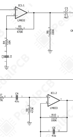
i want to learn how to swap parts the right way instead of guessing and throwing parts around.. i don't know where to start in this circuit for doing any of this, but i've read enough to know i have to calculate the resistor/capacitor values i'd be changing with a formula to get where i want to go.. so i figured i'd start with a basic circuit like this, and ask. i found some calculators at a site called muzique but i don't know how to make use of that properly so now i'm confused..
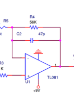
1) what parts of that circuit would i want to look at to get a higher/crisper treble cutoff frequency? i'm not sure if i'm stating this properly.. but i'm trying to stay away from le buzzwords as much as i can ha
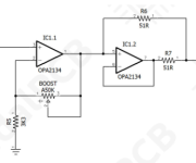
2) if i were to throw an opa2134 in that circuit instead of the lm833 for reasons, what other parts should i want to look at to keep the opa2134 happy?
3) if i'm asking dumb questions, what should i go read before coming back?
schematic is here. https://docs.pedalpcb.com/project/Stumble-PedalPCB.pdf
thank you
it is too warm, not enough treble definition for me.
the low cutoff seems fine, it's just too warm overall in the upper frequencies.
i want to learn how to swap parts the right way instead of guessing and throwing parts around.. i don't know where to start in this circuit for doing any of this, but i've read enough to know i have to calculate the resistor/capacitor values i'd be changing with a formula to get where i want to go.. so i figured i'd start with a basic circuit like this, and ask. i found some calculators at a site called muzique but i don't know how to make use of that properly so now i'm confused..
1) what parts of that circuit would i want to look at to get a higher/crisper treble cutoff frequency? i'm not sure if i'm stating this properly.. but i'm trying to stay away from le buzzwords as much as i can ha
2) if i were to throw an opa2134 in that circuit instead of the lm833 for reasons, what other parts should i want to look at to keep the opa2134 happy?
3) if i'm asking dumb questions, what should i go read before coming back?
schematic is here. https://docs.pedalpcb.com/project/Stumble-PedalPCB.pdf
thank you
Last edited: