The MOD Squad

Tassieviking

Active member
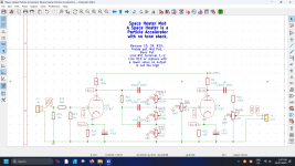
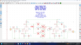
This Thread is for any and all mods that people want to share, I love modding circuits if I can make it more useful to me.
I especially like to add deep switches and Bass switches along with Bright switches so I can use the pedals for Bass and guitar.
I like to use the Tube calculators on the Ampbooks.com website, there is also lots of great info to read on their pages.
And I also use the online tone stack calculator a lot.
 
Last edited:
The first one I am going to screw with.....I mean show is the Ambassador tone stack, that is one weird adaptation of the Marshal or Bassman tone stack.
There is no Bass pot, the knob labeled Bass is in the position the Mid pot is normally in and the original Bass pot is just gone, shorted out.
This results in a tone stack with no bass control so what happens is you either boost the treble with the Treble pot or you cut the treble with the "Bass" (Mid) pot.
Try it here on the TSC : https://www.guitarscience.net/tsc/b...3=22n&RB_pot=LogA&RM_pot=Linear&RT_pot=Linear

I used a 1 ohm resistor for the bass pot but it should be 0 ohms, 1 ohm makes no difference to the TSC, to get a flat response you want the Treble pot on 0 and the "Bass" Mid pot on 10.

For Bass guitar I would use C9-220pF C10-220nF C14-220nF.
Increasing C10 and C14 increases the bottom end, reduces the tapering off of the Bass frequencies.
Increasing C9 brings the treble frequencies down, the frequencies of the tone control drops down where it changes.
Here is a bunch of pictures with different capacitors, read the picture title to see what the values are.

Cheers
Mick

EDIT: If you want to experiment then just place a SIP socket in place of the capacitors so you can change the capacitors easily.
 

Attachments

  • Tone Stack Stock Flat.png
    Tone Stack Stock Flat.png
    287.8 KB · Views: 4
  • Tone Stack Stock Sweep.png
    Tone Stack Stock Sweep.png
    314.8 KB · Views: 4
  • Tone Stack Micks Sweep C9-220pF  C10-220nF  C14-220nF.png
    Tone Stack Micks Sweep C9-220pF C10-220nF C14-220nF.png
    303.8 KB · Views: 3
  • Tone Stack Flat C56pF  C10-220nF  C14-220nF.png
    Tone Stack Flat C56pF C10-220nF C14-220nF.png
    285.2 KB · Views: 3
  • Tone Stack C9 56pF-100pF-220pF-330pF-470pF  C10-220nF  C14-220nF.png
    Tone Stack C9 56pF-100pF-220pF-330pF-470pF C10-220nF C14-220nF.png
    313.9 KB · Views: 3
Last edited:
The Next has to be the Ambassador circuit itself, if you want to use it for Bass I would make the following changes.
Cathode bypass capacitors C11 C12 C13 need to be 22uF but 47uF is ok as well if you play a 5 string.
Coupling capacitors C7 and C8 I would change to 47nF
Remove the bright caps C5 and C6, they are basically a variable High Pass filter that filter out Bass at low volume.

If you just want to use it for guitar and want a deeper tone then just increase C11 C12 C13 a little bit.

I would add extra capacitors across C11 C12 C13 with a switch so I can have Lead / Bass switching, I would also add a switch to switch out the Bright capacitors C5 and C6.
Schematic and other graphs :
 

Attachments

  • Ambassador Bass Mods Schematic.pdf
    Ambassador Bass Mods Schematic.pdf
    76.5 KB · Views: 4
  • C11-220nF.png
    C11-220nF.png
    271 KB · Views: 1
  • C11-22uF.png
    C11-22uF.png
    267.5 KB · Views: 1
  • C11-47uF.png
    C11-47uF.png
    267.6 KB · Views: 1
  • Ambassador V1 Coupling Capacitor 22nF -Clean Pot.png
    Ambassador V1 Coupling Capacitor 22nF -Clean Pot.png
    283.8 KB · Views: 1
  • Ambassador V1 Coupling Capacitor 47nF -Clean Pot.png
    Ambassador V1 Coupling Capacitor 47nF -Clean Pot.png
    275.8 KB · Views: 1
  • C7 coupling cap 47nF Clean pot 500k.png
    C7 coupling cap 47nF Clean pot 500k.png
    257.4 KB · Views: 1
The next mod I am going to show is more about what can be done to the BassDude, I think I only placed the Bright cap on a switch on my first BassDude.
When we look at the Bassdude it becomes obvious it is a copy of an earlier Bassman, the Bassman 5D6-A and the 5E6 both match the BassDude schematic.
The first thing that stands out to me is that we only have one input but the original had two inputs with a common Cathode resistor and capacitor,
since we are only supplying one triode we should really double the resistance of R16 to 1k6 and halve the capacitance of C8 to 120uF.
When I run the graph it does not make much difference if C8 went down to 47uF as far as I am concerned even for Bass.
( I still used a 820R resistor and a 220uF capacitor since it is not really much of a difference to us)

The next thing that really stands out to me and should be the first thing I noticed was that the Bassman used 12AY7 tubes in the preamp and not the 12AX7 the BassDude is supposed to have, that would be a lot less gain in the preamp and I have not even tried it yet.
THERE WILL BE A LARGE LOSS OF OUTPUT WITH LOWER GAIN TUBES I IMAGINE SO IT MIGHT BE TOO LOW WITH 12AY7 TUBES.

Then there is the obvious Bright capacitor C6 which I always place on a switch, the lower the volume the less bass you get with a bright cap so I always place them on a switch.
On the Bassman you have 2 channels and one has a bright cap for guitar and the other channel does not have a bright cap for Bass.

The coupling capacitor C5 is plenty big enough at 22nF for Bass guitar so I leave that alone in this one, 47nF will not hurt though.

I might leave the biggest mod for the next time.
 

Attachments

  • Coupling Capacitor C5.png
    Coupling Capacitor C5.png
    259.1 KB · Views: 1
  • Cathode Capacitor C8.png
    Cathode Capacitor C8.png
    268.5 KB · Views: 1
  • Bright capacitor C6-100pF Volume 100%.png
    Bright capacitor C6-100pF Volume 100%.png
    267.5 KB · Views: 1
  • Bright capacitor C6-100pF Volume 50%.png
    Bright capacitor C6-100pF Volume 50%.png
    270.6 KB · Views: 1
  • Bright capacitor C6-100pF Volume 1%.png
    Bright capacitor C6-100pF Volume 1%.png
    283.4 KB · Views: 1
  • Bassman-5E6-Schematic.pdf
    Bassman-5E6-Schematic.pdf
    964.8 KB · Views: 0
  • Bassman-5D6-A-Schematic.pdf
    Bassman-5D6-A-Schematic.pdf
    726.5 KB · Views: 0
  • Valve comparison.png
    Valve comparison.png
    43.6 KB · Views: 1
Last edited:
This might be one mod on the BassDude that not many have thought of, change a few values on some components and add a second Bright cap on top of R12 and you have a Marshall JTM45 preamp, of course the JTM45 has 2 channels, one with and one without Bright caps so place both caps on a switch if you do this mod.

What do we need to do?
We could place a 68k resistor between the input jack and the PCB but I would not do that, the only real difference is that V2A does not have a cathode capacitor C9 and we need to add the 500pF Bright capacitor on top of R12.
R16-1k6, R17-820R, C8-100uF (120uF), C9-Leave Out, R12-Add a 500pF capacitor over the top, Tone Stack-please yourself with this one.

The more serious modder would also change the tone stack to a classic Marshall tone stack, we would just mount the pots in the box and then wire the resistor and the 3 capacitors to the pots themself and then run 3 wires to the PCB at the right places. ( C7 / C10 junction and R15 / Master junction and also a ground wire )

If you build a JTM45 BassDude then it might make sense to try some 12AY7 tubes in the real BassDude so they sound different, you might just need one 12AY7 and one 12AX7 in the BassDude but you just have to experiment with different tubes.
 

Attachments

Last edited:
Bath Tub Reverb- SamuelG did a very nice mod to his Bath Tub pedal by adding a normal/deep/bass switch to his build.
All it involves is to add more capacitance to C2 to allow more deep frequencies through, he did this by installing C2 and leaving the legs long enough to add some wires to run to some capacitors,a DPDT ON-ON-ON switch and 2 resistors.
You will need the C2 capacitor 22nF 630V, another 22nF 630V capacitor and a 100nF 630V capacitor, and also 2 resistors about 2M ohm as well as a switch DPDT ON-ON-ON.
Here are the pictures which I have "borrowed" (nicked) from SamuelD's posts :
 

Attachments

  • IMG_7767.jpeg
    IMG_7767.jpeg
    479.6 KB · Views: 4
  • IMG_7772.jpeg
    IMG_7772.jpeg
    597.4 KB · Views: 4
  • IMG_7775.jpeg
    IMG_7775.jpeg
    503.4 KB · Views: 4
  • IMG_7766.jpeg
    IMG_7766.jpeg
    366.4 KB · Views: 3
  • Bath Tub Reverb Bass Mod 3way SW.png
    Bath Tub Reverb Bass Mod 3way SW.png
    265.2 KB · Views: 3
Bath Tub Reverb- SamuelG did a very nice mod to his Bath Tub pedal by adding a normal/deep/bass switch to his build.
Here are the pictures which I have "borrowed" (nicked) from SamuelD's posts :
Borrow my pics as much as you like… since I stole the whole idea from you 😎
But I AM working on a Bathtub mod to use the ABE module! I’ll post if I get it to work.
 
Back
Top