Cybercow
Well-known member
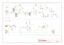
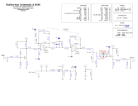
After finding the Kokko Distortion schematic, I traced the Kokko unit I had to check if the one I found is correct. My tracing matched the found schematic perfectly. But when I breadboarded it, it didn't sound like the original. I repeated the breadboarding a few times to be sure I was doing it right. But it just didn't sound right. So I had to tweak some things to get it to sound like the original. The most impactful change was to use an LM358 (0.3V/µs slew-rate - like an LM308/µA308/OP07) in place of the original LM4558 (1.7V/µs slew-rate). I also tweaked few resistor and a coupla cap values.
Original schematic . . . . Traced and updated schematic . . . .


Then, some help from @rwl and Bill Carrigan, I was able to get a set of Gerbers for PCB fabrication. (Thanks fellas!)
Then on to the builds themselves . . . .


I also wanted to have one where the Gain control was actually two separate controls instead of a dual-ganged pot. I used a 9mm Alph concentric pot so I could use the same PCB and drill template. Having the Gain pot split into two controls adds a bit more dimension to the adjustability of the two separate gain stages. And I think the finished build still looks good too.


Thanks for looking. Happy building folks!
Original schematic . . . . Traced and updated schematic . . . .
Then, some help from @rwl and Bill Carrigan, I was able to get a set of Gerbers for PCB fabrication. (Thanks fellas!)
Then on to the builds themselves . . . .
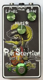
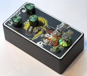
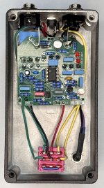
I also wanted to have one where the Gain control was actually two separate controls instead of a dual-ganged pot. I used a 9mm Alph concentric pot so I could use the same PCB and drill template. Having the Gain pot split into two controls adds a bit more dimension to the adjustability of the two separate gain stages. And I think the finished build still looks good too.
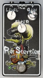
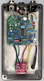
Thanks for looking. Happy building folks!
