Thermionic distortion issue

alienas

Member
Hi people,
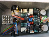
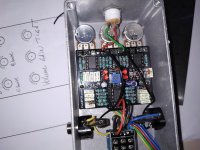
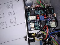
i've built the thermionic distortion and it works but not completly...
First i don't have the true bypass, when not engaged i have no sound but the power led is on.
When engaged the power led is off but the tone is not splendid. I have ton's of gain with the gain pot set to min. Other thing : all the clipping leds are not working : only the leds on the left side are flashing while playing, the right side stay off.

When i wired the main board to the footswitch pcb, i used the documentation of the "uber drive" pedal because the thermionic documents are not accurate. No footswitch pcb on the user guide i found. So maybe i swapped some wires...

Any help would be appreciated, thanks
 

Attachments

  • IMG_20210520_101301.jpg
    IMG_20210520_101301.jpg
    1 MB · Views: 31
  • IMG_20210520_101245.jpg
    IMG_20210520_101245.jpg
    913.4 KB · Views: 33
  • IMG_20210520_101237.jpg
    IMG_20210520_101237.jpg
    858.4 KB · Views: 33
You're on the right track, it's most likely a switch problem.

Why have you used the Kliché 3PDT? It's specifically designed for the Kliché (I've no idea what the difference is with a PedalPCB regular 3PDT breakout board, as I've used neither).

D2 & D5 look like they need to be reflowed with solder, not that it will be part of your main problem. Hard to tell, 'cause no photo of the solder side of the board. The component side may not look right, even when a good join on the solder side is made.

I wouldn't worry about the LEDs flashing or not. I can't tell from the PCB diagram online, nor the build doc, nor from your photos which set of LEDs is to ground and which are in the feedback loop of U1.2, but I'll hazard a guess that the ones on your board closest to C14 are the ones that go to ground. They'll be the ones that flash, whereas the the ones in the op-amp loop may not reach the clipping threshold and thus won't flash (I'm guessin' not as much gain earlier in the circuit, they'll flash on big peaks).

For sure you've got the bypass LED's anode and kathode wired backwards if it's on when bypassed.

I'd hazard another guess that you've maybe wired the jacks to the 3PDT breakout backwards. Is there any labelling on the breakout board?

R21 and R9 look like they need to be reflowed as well (side closest to the IC).

I'd take it out of the box, check all solder-joins and any that look suspect (like gain 1) and reflow them.

Have you got another 3PDT switch? Maybe desolder the wires from the Kliché 3PDT board, and rewire directly to a new switch (desoldering the daughterboard from the 3PDT would be too troublesome).

Get your DMM set on stun (beep mode) and check for continuity. The Polarised caps are correct, the ICs are oriented correctly, D1 correct... Go to one of the online resistor colour-code calcs (Digikey for example) and check all your resistors are correct and you haven' t subbed a 4k7 for 47k, that sort of thing. That's all I've got.
 
Last edited:
Other thing : all the clipping leds are not working : only the leds on the left side are flashing while playing, the right side stay off.

just built one of these and its the same way, mine the right side will barely come on when pushed really hard while the left are pulsing madly. I would hazard a guess your fine there.

Ag
 
Well i used the board that was given with my kit. As i made another kit with a footswitch board that was working great, i used the board instead of nothing, I did not know that kliché was another effet circuit, and my eyes are old. The "tight" button is maybe reversed also, as it gives more bite when set on 0. As soon as i have a new footswitch i fix the circuit.
Thanks for answering so fast...
 
in fact, the problem was that i had not well soldered the diodes and part of the resistors on both sides. I don't know much about several layers PCBs. So i put a new 3pdt switch and resoldered a few components, and it works ok. Nice sound indeed. Just the "tight" control is reversed (i think), i would have put the pot upside down? And it would still fit inside the box?
I did not play with the central trimmer yet.... More tests tomorrow...
 
These are two layer PCBs with thru-plated holes. As long as you solder one side correctly, you're good to go. The TIGHT control is like a reverse Bass control. Turn it clockwise to reduce the bass and tighten up the tone.
 
Thanks. Just a question about 2 layers PCBs...
It seems that the physical layout of the components on the board is out of scope, as the resistors, IC's and capacitors are layed out symmetricaly, all the res in one part, all the capa in on another part of the board, with no relation with the schematic. You see what i mean.
I am an amp maker/builder, and if i do that on a amplifier, it will result bad sound, noises and interferences.
It seems its not a problem in a pedal, what do you think?
Thanks
 
Voltage and current levels within a pedal are typically too low for any noticeable crosstalk between traces, as far as I know. At least I’ve never had a problem (that I know about)
 
all the res in one part, all the capa in on another part of the board, with no relation with the schematic.

It's not quite like that. The component placement generally does follow signal flow. The capacitors and resistors are arranged with some uniformity, but they are generally placed along with their counterparts.

Of course every now and then there are a couple stray components, but it'd be closer to imagine the circuit divided into blocks, then those blocks are arranged into a symmetrical orientation... components aren't usually just thrown all over the board so they look pretty.

There are some "black sheep" (particularly a few of the older boards), but I generally try to pay attention to trace length and placement vs net impedance / signal gain / etc. I try to keep LFOs away from the audio path, isolate the ground planes, etc.


There seems to be a bit of a misconception that a layout has to look messy in order to be efficient, and while I agree 100% efficiency probably would not factor in cosmetic appearance at all, I like to believe there is a middle ground where a layout can both look presentable and still work properly and within spec. Sometimes it bites me in the ass, but it's a struggle I'm willing to deal with. :ROFLMAO:

Just to be clear, I'm not saying anyone is wrong for questioning my methods, just that it's not always* quite as random and chaotic as it might appear. *sometimes it is
 
Last edited by a moderator:
Back
Top