This Week on the Breadboard: MOSFET Driver Redux

Chuck D. Bones

Circuit Wizard
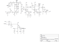
I was chatting with BuGG about the MOSFET Driver circuit and he encouraged me to have a go at a redesign, so here's my first stab at it. The original had a Whole Lotta Gain and this version is true to form on that front. With everything dimed, the end-to-end gain is 115dB. I got rid of the extraneous opamp buffer up front and added a Timmy-style BASS control to the 1st stage. I also added LED soft clippers to keep the opamp from saturating. Q2 will saturate long before the LEDs turn on. U1 has the same gain range as before, from 0dB to 49dB. I used an LF356 for U1, but any FET-input opamp will work. In place of the Bias1 trimpot, Q1 now has a VOICE switch. In the left position, Q1's gain rolls off below 600Hz to give it a Bright Channel tone, good for humbuckers. In the center (off) position, Q1's gain is lowered to 12dB for a cleaner, low-gain tone. In the right position, Q1 runs wide open at over 40dB gain. Q2 has a Gain Trim, similar to the Bias2 trimpot, but now the bias is constant. Q2's gain is adjustable from 17dB to 40dB. That's followed by a Timmy-style TREBLE control and a source-follower output buffer. The MOSFETs run on +25V for HUGE volume and headroom. The max output is 20Vp-p. Take that, tube amplifiers! The two MOSFET gain stages are reminiscent of the Box of Rocks, so for now I'm calling this the Box of Timmys.

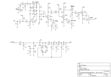
BoT v0.5.png
 
Last edited:
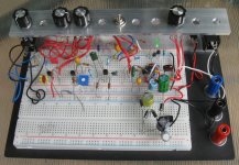
The LEDs are 3mm green diffuse. The ones with the annoying little plastic block on the leads (upper right). Charge pump: lower right.
Top red power bus: Vref. Blue bus below that: GND, then Vcc, GND, Vdd & GND.

Box of Timmys v0.5 breadboard 02.jpg
 
Gotta push those electrons uphill!

Maybe it's a Bag of Dicks-on charge pump.

But seriously folks, it's a modification of the Dickson which is a modification of the Cockroft-Walton...
Because there are hardly any truly original circuit designs. This voltage multiplier design shows up in the application notes from charge pump datasheets. You can also find it in the TC Electronics Integrated Preamp. The Integrated Preamp contains a 4x multiplier, this one is only a 3x multiplier.
 
Is it Karate-Kid switchable? ie some circuits boosted to 18v sound good at 9v — so can dickson be ...off?
I see what you did there. ;)
Sure, the Vdd voltage can be lowered, and I intend to try that. We would need to reset the bias on Q1 & Q2 by changing the source resistors, drain resistors, Vref or a combination of the three. The MOSFETs could be run on an adjustable Vref that is different from the opamp Vref. Hmmmm. :unsure:

Any issues using a dual opamp, with the second half as the buffer replacing the mosfet emitter follower at the output?

It is bad practice to put the two halves of a dual opamp far apart in the signal chain. Particularly so when there is significant gain between the two halves, as it is in this circuit. It invites oscillation. I understand that builders want to minimize the number of devices in their inventory, but come on, there are plenty of pedal circuits that have, or should have, an odd number of opamps. How much trouble is it to stock some TL071s?
 
Last edited:
I'm still tweaking the TREBLE control, and will experiment with variable Vdd & bias this weekend. I think the basic circuit design is stable, it's just down to the fine tuning. I'm hoping some of y'all breadboard this beast and offer some feedback on what you like and don't like.
 
I'm still tweaking the TREBLE control, and will experiment with variable Vdd & bias this weekend. I think the basic circuit design is stable, it's just down to the fine tuning. I'm hoping some of y'all breadboard this beast and offer some feedback on what you like and don't like.

I’m just about finished populating my Protoboard and have been wanting either the MOSFET driver or the Cattle driver so this thread is right on time!

And your flanger thread!
 
I was surprised that you had a charge pump in the initial version since you're not the biggest fanboy of them I believe... ;)
 
It's true! I was a bit wary due to the high gain and the fact that the circuit was built on a protoboard. But I thought I'd give it a go and it worked great with the charge pump.
 
One last tweak:
R8 = 150K
C6 = 470pF (C6 = 1nF for a little more "presence")

I tried an auto-bias for the MOSFETs, but it did not work as well as the set-and-forget trimmer.

I like the 9V rail version better. More than enough volume and better tone IMO. Here are some freq response plots:

DRIVE sweep. TREBLE, BASS & Gain Trim dimed, VOICE set for Loud. Higher DRIVE settings roll-off the high-freq response.
BoT v0.6 drive.png

BASS sweep. DRIVE, TREBLE & Gain Trim dimed, VOICE set for Loud.
BoT v0.6 bass.png

TREBLE sweep. DRIVE, BASS & Gain Trim dimed, VOICE set for Loud.
BoT v0.6 treble.png

VOICE switch. DRIVE, TREBLE, BASS & Gain Trim dimed. Red is Loud, Blue is Tight, Green is Low-Gain.
BoT v0.6 voice.png

Gain Trim sweep. DRIVE, TREBLE & BASS dimed, VOICE set for Loud. Notice how backing off on the Gain Trim extends the high-freq response.
BoT v0.6 gain trim.png

Treble Boost. DRIVE = 8:00, BASS = 7:00, TREBLE = 5:00, Gain Trim = zero, VOICE = Tight.
BoT v0.6 treble boost.png
 
Well yes & no...

I increased the BASS pot to C10K, removed R4 and reduced C5 to 100nF. Gives the BASS control a few dB more range in both directions. C4 doesn't need to be any larger than 22uF unless you're going to run a down-tuned bass thru this beast.

TL071 is preferred for U1 because it's low-noise, but any single FET-input opamp will do. Maybe make a spot to install an optional cap between pins 1 & 8 so that CA3130 & CA3140 will qualify.

Make all of the electrolytics tantalum except C14 & C15 can be aluminum.
 
Back
Top