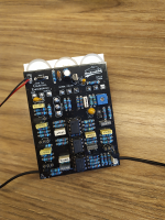
This Week on the Breadboard: Phase 90

sure, but adding an entirely new digital LFO chip is a whole different thing. my goal with mods on classic pedals is to still be able to access all of the classic sounds (ideally by setting the knobs to noon or one or the other extreme) but having many more usable options available. so in the case of the LFO, i still want that original "shark fin" pseudo-triangle shape available, but i also want to the LED to ramp in sync with it.
 
Last edited:
I'll say one more thing and then we can drop this line of discussion. The STOMPLFO is capable of generating 8 different waveforms. You don't have to use all of them. Two of the waveforms are generated from lookup tables and I figured out the location and syntax for those tables (it wasn't all that hard). So if you want the "shark fin" waveform, you can replace the SINE or SWEEP wave table with a SHARK wave table. The STOMOPLFO doesn't tick and it supports offset (COLOUR) & amplitude (DEPTH) controls inside the chip. The only thing the user needs to provide is 5V power and an RC filter for the PCM output. It worked a treat in the 'Lectric Mama. It's just another way to get the classic Phase 90 tone.
 
okay i didn't know that, that is indeed intriguing. i have a different LFO designed (again only in falstad, haven't had a chance to put it on the breadboard) that, similar to the TR-2 or sea machine/space spiral LFO, variably clips the waveform so you can go continuously from shark-triangle to clipped-triangle-pseudo-sine to square wave. but for a deluxe edition with a second footswitch for tap tempo that's probably what i'd go with. a rotary switch for shark-sine-square would probably be as useful as a continuously variable knob, as cool as that idea seems to me. and then have five more shapes available.
 
here's a simpler version of the LFO LED. if you're re-designing the circuit from scratch there are several other options you could go with as we've discussed previously in this thread, but if you just want to modify an existing pedal or PCB, this is probably the easiest way to do it while having the LED ramp with the LFO:

 
I'd have done it differently.
No resistor in parallel with the LED. One resistor from LED cathode to GND, another from LED cathode to Vcc. Set the ratio so that the LED current goes to zero at the bottom end of the LFO waveform, set the parallel resistance for the desired LED brightness at the top of the waveform.
Saves power and less stress on the opamp.
 
Last edited:
...a hypothetical non-superbright simulation LED with a peak brightness at 10mA, i guess...

multiply the resistor values by 10 to get a peak 1mA current
 
Last edited:
Back
Top